7.8 NMMA TC-W3® Filterability Test
7.8.1 Scope
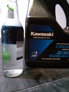
This test is designed to determine the tendency of an oil to form a gel, or precipitate,
which can plug oil filter screens in Two-Stroke-Cycle engine Oil Injection Systems. It simulates a
problem which can be encountered in oil injection systems where ashless NMMA Certified Two-
Stroke-Cycle Engine Oils are contaminated with calcium containing low ash Two-Stroke-Cycle Engine
Oils in presence of small amounts of water (i.e., water of condensation). If the candidate oil is not
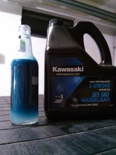
dyed, .05% of the Automate Blue 8 shall be added before testing. This is to aid the tester in
detecting contaminates in the neat oil.
7.8.2 Apparatus
7.8.2.1 4 oz. or 8 oz. Small glass or clear plastic bottles
7.8.2.2 25 ml burette (See Note 1)
7.8.2.3 Filter holder (Millipore xx300 01200 effective filter area » 0.6 cm2)
(See Note 2)
7.8.2.4 Outboard Marine Corporation Filter Screen 150 Micron Mesh Size
7.8.2.5 Stopwatch capable of timing sequential events (a Heathkit Model GE-
1201E or equivalent can be used)
NOTE 1: To insure that there are no restrictions to the oil flow in the burette, a Teflon
stopcock with a minimum opening of 1.8 mm must be used. Likewise the tip of the burette must
have an opening of 1.8 mm or greater.
NOTE 2: Since Standard Reference Oils with accurate flow rates are not used in this test
procedure, calculate the effective filter screen area using the inner diameter of the filter ”O” ring.
7.8.3 Reagents and Materials
7.8.3.1 Calcium containing low ash Two-Stroke-Cycle Engine Oil (CITGO
935111).
7.8.3.2 93738 NMMA Reference
7.8.3.3 Water: For the purposes of this test use distilled water
7.8.3.4 Candidate NMMA Two-Stroke-Cycle Engine Oil
7.8.4 Sample Preparation
9
7.8.4.1 Volumetrically and at room temperature thoroughly mix 100 ml of
Candidate Oil with 100 ml of CITGO 935111 Two-Stroke-Cycle Engine Oil.
7.8.4.2 Separate the mixed oil into an 80 ml portion and a 120 ml portion.
7.8.4.3 Place the 80 ml portion of mixed oil in sealable bottle and set sample
aside undisturbed for use as a control sample. Each Candidate Oil will have its own control sample.
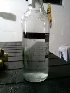
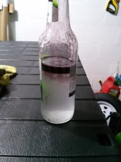
7.8.4.4 Place the 120 ml portion of mixed oil in a sealable container. Add
0.25 Volume Percent distilled water and vigorously shake by hand.
7.8.4.5 Separate the 120 ml water containing mixed oil into 2-60 ml portions,
place in sealable bottles, and set aside undisturbed for 48 hours at room temperature.
NOTE: A 60 ml sample amount was selected in order to put all of the sample through
the filter mechanism, 50 ml for actual test timing and 10 ml for filling and leveling of burette. This
should help in introducing into the burette any heavy matter, which may have migrated to the bottom
of the sample bottle.
7.8.5 Filterability at room temperature
7.8.5.1 Set up the 25 ml burette equipped with a filter holder with discs of
OMC Filter Screen material cut to fit the holder.
7.8.5.2 The control oil flow rate is determined by placing a sample of the
control oil in the burette and passing enough of the control oil though the filter holder to remove air
bubbles. The burette is then filled with control oil to a level 1-2 cm above the “O” mark; the stopcock
is opened all the way; and the flow time of each successive 5 ml of oil is measured between the “O”
and 25 ml graduations.
The flow rate of each 5 ml portion of oil is calculated using Equation (1).
Equation (1) Flow rate = (A)/(B)/(C)
Where A = Volume of oil (ml)
B = Flow Time (sec)
C = Area of Filter (cm2)
7.8.5.3 To determine the test oil flow rate, the flow times of the control oil
are first determined as outlined in step 7.8.5.2 using the same filter screen and filter holder the
control oil level in the burette is reduced to the lowers level which allows no air bubbles below the
stopcock. The burette is filled with the test oil to level 1-2 cm above “O” mark. Open the stopcock all
the way and the flow time for each successive ml of oil is measured between the “O” and 25 ml
graduation.
The flow rate for each 5 ml portion of test oil is calculated using Equation (1).
10
7.8.5.4 The percent decrease in flow rate of the test oil relative to the new oil
is calculated from the final oil flow rates (between 10 and 25 ml measured with the same filter disc.)
using Equation 2.
Equation (2) Percent decrease in flow rate = [(b – a) x 100]/a
Where a = Final new oil flow rate
b = Final test oil flow rate
7.8.6 Test results
7.8.6.1 Tests on candidate engine oils must be run in duplicate and the
candidate oil test report is to contain the following information:
(1) Candidate oil identification
(2) New oil flow rate at 5, 10, 15, 20, 25 ml
(3) Test oil flow rate at 5, 10, 15, 20, 25 ml
(4) Percent change in flow rate for each test
7.8.7 Requirements
7.8.7.1 Results from candidate oils must have a decrease in test oil flow rate
of less than 20 percent in comparison to the new oil flow rate.
7.8.8 Sample Calculations
7.8.8.1 MEASUREMENTS OF FLOW TIMES. The flow shown in the example in
Table 2, is for the 5 ml portion of oil ending at the indicated volume. Flow times were measured with
a digital stopwatch capable of timing sequential events (i.e., the time for the new oil to flow from the
5 ml mark to the 10 ml mark was 6.75 s).
7.8.8.2 CALCULATIONS OF FLOW RATE. The flow rate is calculated from
Equation (1). Thus for the first 5 ml of new oil, the flow rate is:
Flow rate = (A)/(B)/(C)
= (5ml)/(5.61 s)/(0.636 cm2)
= 140 ml per sec per cm2
Where A = Volume of oil (ml)
B = Flow time (sec)
C = Area of filter (cm2)
TABLE 2 – FLOW TIMES AT INDICATED VOLUMES
Volume Reference Oil Test Sample Oil
sec sec ml
5 5.61 7.61
10 6.75 11.24
15 6.77 16.00
20 6.81 22.01
25 7.61 30.99
11
The calculated flow rates obtained using Equation (1) for the rest of the sample are shown in Table
3.
7.8.8.3 Calculation of percent decrease in flow rate
The percent decrease in flow rate is:
Percent Decrease = (b - a)/a
= (0.25 – 1.1)/1.10
= -77.3 percent
Where a = Final new oil flow rate
Where b = Final test oil flow rate
")