2011 Superjet Defoam, RRP Adjustable Footholds Install, and Engine Mods

jbex4ford

Certified YouTube Mechanic
Location
West Michigan
I’ve been wanting to do a write up on my latest project that I just finished a couple of weeks ago. I have a 2011 superjet that I installed RRP adjustable footholds in it. I ended up defoaming and refoaming my tray as well. Along with this, I also bought a Zeeltronics Y62T CDI for it last fall when they became available. I purchased my CDI from Paul at LPW, can't say enough good things about him. My superjet has a 62T cylinder with a factory limited pipe on it, but it just didn't have the lower end snap that I was looking for. After talking to Paul on the phone, he gave me a couple of suggestion for my motor on how to gain some low end performance that I knew that I could do myself being a machinist. I ported it myself with yamanube's porting templates before I ever talked to Paul, but more on all of this later.

So back to my hull, I suspected that my foam in the tray was water logged, being that the back of my ski always felt heavy. When I started to remove my old footholds, my suspicions was confirmed, that the foam was water logged. I ordered a set of RRP adjustable footholds from Riva in the middle of summer last year (2021). Riva called me in April and told me that my footholds were finally in stock after being on back order for quite sometime. After doing a quit a bit of research and find a couple of good threads that some different member's write up's on them, I wanted to do the same.

I found this tread to be very handy https://www.x-h2o.com/threads/superjet-defoam-and-rrp-adjustable-foot-hold-install.188830/

Just like Brett point out in his post, I didn’t receive any instructions with my footholds either. I’ll point out mistakes that I made, and hopefully others can learn from my mistakes. I started on the Friday of Memorial Day weekend removing my old turf and started cutting the new box’s in. Even though that I received my footholds in April, I wanted to wait until I was sure that I had everything that I was going to need to finish the job, fiberglass, resin, underpad, new turf. I glassed in my new footholds with some 1708 biax, and cover it with some 8oz twill. I have to thanks Schicks for helping me on what fiberglass he uses when he glasses footholds in. I also used thickened epoxied to adhere the RRP boxes, that come in the set to the inside walls of the gunwales.

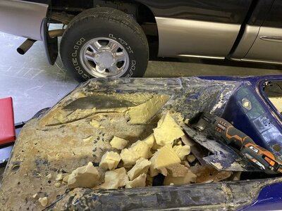
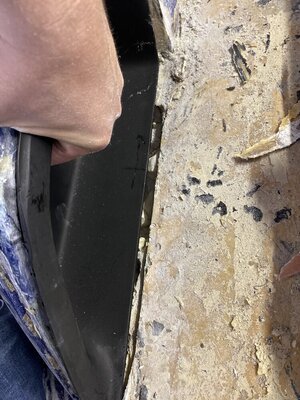
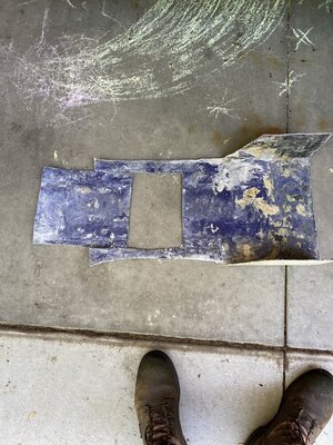
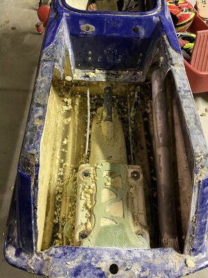
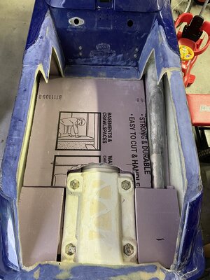
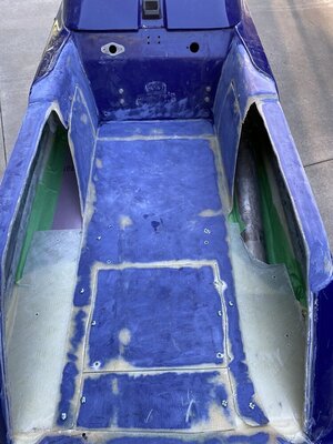
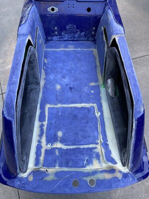
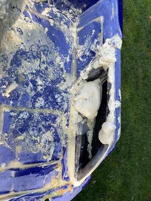
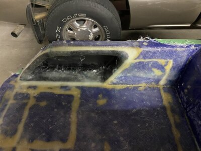
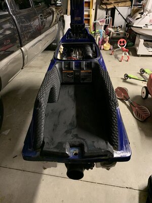
Here's a picture of my tray before I started removing the old turf, and when I started removing the turf. I started with cutting my left foothold first. When I laid out my cut lines for installing my new footholds, one problem that I ran into was that when I cut away my old footholds, I cut a little farther into the bottom of my tray than what I needed to. As you can see from the picture. I ended up doing the same thing on the right side as well, but just more inboard. Being that I this is the 1st superjet tray that I have cut apart, I wanted to make sure that I stayed away from the exhaust tube.. Knowing what I know now, I could have easily cut straight down from the radius of the inside of the tray, and I would not hit the exhaust tube. I cut out the the rest of my tray 2" from the top and 2" from the front. I cut around the pump tunnel, but after doing that I ended up cutting out that piece as well.
 

Attachments

  • 67535878958__5AF43A26-2692-48EC-82D4-1EA10DAAC9C6.JPEG
    67535878958__5AF43A26-2692-48EC-82D4-1EA10DAAC9C6.JPEG
    191.3 KB · Views: 92
  • 67536051751__DA5C216D-4523-4B38-963A-58FE4205874E.JPEG
    67536051751__DA5C216D-4523-4B38-963A-58FE4205874E.JPEG
    201.1 KB · Views: 80
  • IMG_9263.JPEG
    IMG_9263.JPEG
    221.2 KB · Views: 66
  • IMG_9257.JPEG
    IMG_9257.JPEG
    201.2 KB · Views: 68
  • IMG_9261.JPEG
    IMG_9261.JPEG
    212.7 KB · Views: 72
  • 67535234108__891D84E1-A309-4381-A449-29BE179F3D2C.JPEG
    67535234108__891D84E1-A309-4381-A449-29BE179F3D2C.JPEG
    164 KB · Views: 77
jbex4ford

Certified YouTube Mechanic
Location
West Michigan
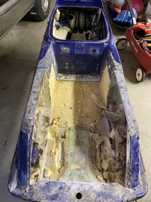
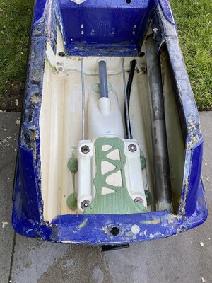
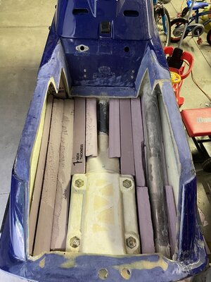
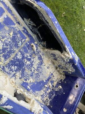
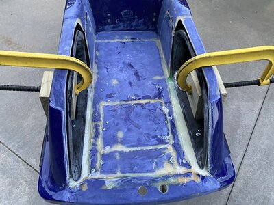
Once I had the majority of my old foam removed, I power washed out what was left. The original adhesive that Yamaha used to bond the top and bottom together, comes off really easy with a putty knife and a heat gun. I stacked 2" foam vertically and I put a piece of 1" horizontally to refoam my hull. Before I did that I added a second 3/8" cooling line, and I also added a 5/8" stainless tube, so that way if I want to add trim some day, I will be able to easily. I wanted to keep the stock bilge, that's why I added another 3/8" line. Another thing that I did, but sorry I forgot to take a picture, is I applied thickened epoxied around all of the openings for all of the tubes that run threw the bulk head to the pump. Along with doing this, I glassed in both sides of the factory openings where Yamaha filled the hull with foam. Once, my resin dried, I then went back and applied 5200 to the edges of the bulk head, the steering cable tube, both cooling lines, the stock bilge tube, and the exhaust tube. Along with doing this, I also reinforced the bond line in the back of my hull. I laid 4" wide strips of 1708 on the bond lines.

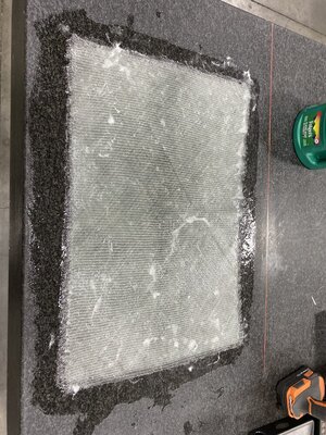
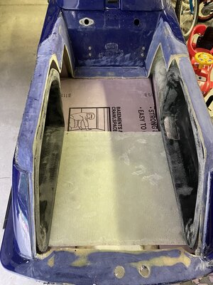
After the 5200 dried, here's how I went about fixing the gaps on the bottom of my tray, that I did when I was fitting the new footholds. I made my own sheet of fiberglass , I used 2 layers of 1708 biax, and I used a surface plate at work, so that I knew I would have a nice flat sheet, that I could epoxy the bottoms of my new footholds and the part of the tray that I cut out being that I cut it into 2 pieces.
 

Attachments

  • IMG_9281.JPEG
    IMG_9281.JPEG
    231.8 KB · Views: 71
  • IMG_9433.JPEG
    IMG_9433.JPEG
    169.2 KB · Views: 71
  • IMG_9434.JPEG
    IMG_9434.JPEG
    168.5 KB · Views: 71
  • 67571614720__CDF06C28-409F-4861-9053-36793D659CD6.JPEG
    67571614720__CDF06C28-409F-4861-9053-36793D659CD6.JPEG
    250.8 KB · Views: 72
  • IMG_9435.JPEG
    IMG_9435.JPEG
    181.7 KB · Views: 69
Last edited:

jbex4ford

Certified YouTube Mechanic
Location
West Michigan
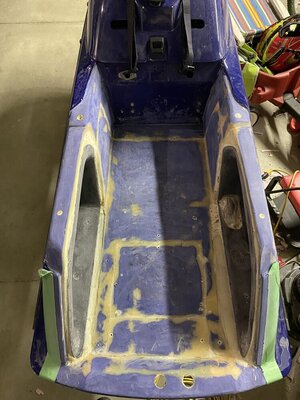
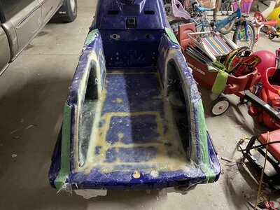
Here's a couple of photos that I took, right before I re-epoxied everything back together. Another thing that I did to was, I taped all of my seems on the foam, being that I planned on using 2 part expanding foam from US Composites around my new footholds as well as the gunwales. But before I did this, I poured expanding foam under the sheet of fiberglass that I made. The reason I did this, is because I figured that's where most of the impact (being too that I'm not getting any thinner as I get older :D) is going to take place, and I wanted to make my tray as strong as possible.
 

Attachments

  • IMG_9439.JPEG
    IMG_9439.JPEG
    136.9 KB · Views: 73
  • IMG_9455.JPEG
    IMG_9455.JPEG
    171.5 KB · Views: 73
  • IMG_9452.JPEG
    IMG_9452.JPEG
    185.9 KB · Views: 70

jbex4ford

Certified YouTube Mechanic
Location
West Michigan
I thickened epoxied my old inserts that I cut out as well as my new foothold to the fiberglass sheet that I made. Instead of using rivets, I used sheet metal screw to hold everything together while the epoxy dried. I made my own set of aluminum washers, I used1/16” aluminum flat stock just to have something to hold the edges of the piece that I cut out of my tray. Once the resin dried, I removed all of the sheet metal screws. I sanded the thickened epoxy before I filled the gunwales with 2 part expanding foam from US Composites. Fun fact that I learned, is that you need bigger than a 5/8” to pour the expanded foam in. I tried using that size, and what a mess that turned into. The foam that I poured into the gunwales, started to expand, and closed off my opening before I could finish pouring what I had mixed up, so there I sat with about 10oz of 2 part expanding foam in a cup realizing that I couldn’t do anything with. Good Times!

So once that disaster was finished, I was mix up some more expanding foam, and I was able to pour the foam in around the opening of my new footholds. I had them all tapped off at first, hoping that would help for forming the edges, but it wasn’t that big of a deal, being that expanding foam cuts and sands really easily.
 

Attachments

  • IMG_9490.JPEG
    IMG_9490.JPEG
    271.7 KB · Views: 56
  • IMG_9498.JPEG
    IMG_9498.JPEG
    160.3 KB · Views: 59
  • IMG_9489.JPEG
    IMG_9489.JPEG
    270.7 KB · Views: 56
  • IMG_9456.JPEG
    IMG_9456.JPEG
    188.1 KB · Views: 60

jbex4ford

Certified YouTube Mechanic
Location
West Michigan
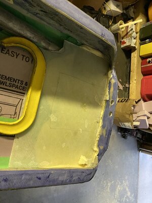
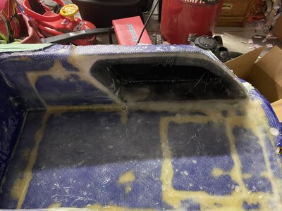
Once I had my tray sanded down again, it was time to lay some fiberglass. For my repair, I used 1 layer of 1708 biax and 1 layer of 8oz twil to cover my old tray, I figured this would be a stronger, than just cutting strips to cover the edges of my footholds and where I cut apart the tray. I laid them at the same time so that way I would have a mono bond for my fiberglass repair.
 

Attachments

  • IMG_9506.JPEG
    IMG_9506.JPEG
    192.2 KB · Views: 61
  • IMG_9504.JPEG
    IMG_9504.JPEG
    160.8 KB · Views: 63
  • IMG_9505.JPEG
    IMG_9505.JPEG
    165.9 KB · Views: 75

jbex4ford

Certified YouTube Mechanic
Location
West Michigan
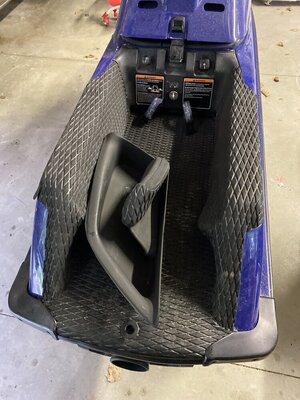
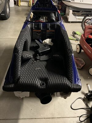
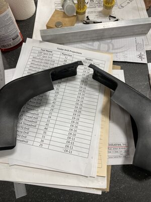
I didn't end up gel coating over my fiberglass that I relayed. I just went with black diamond cut hydro turf on the gunwales and my foot tray. I put down the 1" under padding on my foot tray. I wanted it to be nice and comfy when I ride. Another thing that I did, was I had to cut back the upper corners of the stock end rail caps. If memory servers me correctly I believe that I went in 2" from the edges towards the foot tray, but I'm not 100% sure on that. I had to do this because of the 1" underpad was pushing up the edges to much to be able to use the stock holes that are already drilled in the bond line.
 

Attachments

  • IMG_3125.JPEG
    IMG_3125.JPEG
    138.1 KB · Views: 66
  • IMG_3127.JPEG
    IMG_3127.JPEG
    146.5 KB · Views: 67
  • 68183248927__65E533D6-19CA-4A8C-A29B-2513964FA729.JPEG
    68183248927__65E533D6-19CA-4A8C-A29B-2513964FA729.JPEG
    147.6 KB · Views: 71
Excellent work! I put adjustable footholds in my superjet as well I just didn't refoam the tray as it had already been done. I'll also say that the adjustable footholds make turfing the tray much easier to do.
 

jbex4ford

Certified YouTube Mechanic
Location
West Michigan
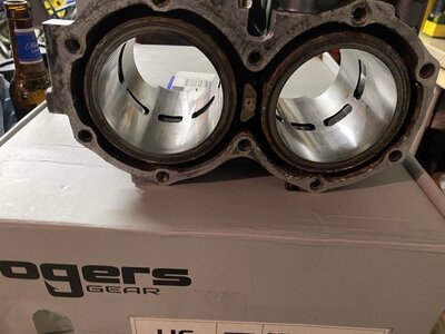
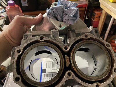
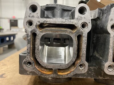
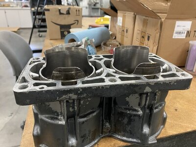
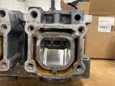
Sorry I have been totally slacking on finishing this write up. Here’s a couple of photos of my port job and a link to the video of when I machined the bottom of my cylinder.

Here's the a link to my YouTube video on when machined the bottom of the cylinder
.

I ended machining .024" off the bottom of my cylinder, then I had to recut my domes, I have an ADA head on my motor, to reestablish the correct squish at .050"
Man I am super happy how this thing runs now with the Zeeltronics and lowering my port timing, my motor has great power all the way through the RPM range. From right out of the hole, to wide open. I really can't say thank you enough to Paul for his help and suggestions with my motor.
 

Attachments

  • IMG_8399.JPEG
    IMG_8399.JPEG
    115.6 KB · Views: 38
  • IMG_8400.JPEG
    IMG_8400.JPEG
    158.6 KB · Views: 35
  • IMG_8405.JPEG
    IMG_8405.JPEG
    160.3 KB · Views: 32
  • IMG_8406.JPEG
    IMG_8406.JPEG
    166.1 KB · Views: 32
  • IMG_8409.JPEG
    IMG_8409.JPEG
    137.4 KB · Views: 36

jbex4ford

Certified YouTube Mechanic
Location
West Michigan
Excellent work! I put adjustable footholds in my superjet as well I just didn't refoam the tray as it had already been done. I'll also say that the adjustable footholds make turfing the tray much easier to do.
Hey thanks fastgtfairlane! I completely agree with you on turfing adjustable footholds. I do really like how they widen your stance in the tray as well. My kids love to ride on it with me, that was the biggest draw to me to install adjustable foot holds. I liked that I can remove the foothold when we go to a lake to mess around, or if I ride it in the surf, I can easily reinstall them for that.

 
Last edited:

jbex4ford

Certified YouTube Mechanic
Location
West Michigan
Sorry I have been totally slacking on finishing this write up. Here’s a couple of photos of my port job and a link to the video of when I machined the bottom of my cylinder.

Here's the a link to my YouTube video on when machined the bottom of the cylinder
.

I ended machining .024" off the bottom of my cylinder, then I had to recut my domes, I have an ADA head on my motor, to reestablish the correct squish at .050"
Man I am super happy how this thing runs now with the Zeeltronics and lowering my port timing, my motor has great power all the way through the RPM range. From right out of the hole, to wide open. I really can't say thank you enough to Paul for his help and suggestions with my motor.
I realized that I forgot to add, that I had Alex at PFM lighten my flywheel for me as well.
 

jbex4ford

Certified YouTube Mechanic
Location
West Michigan
What is the Max RPM now?

How many Total Hours to re-do the Tray, start to finish?
That's a really good question. My best guess would be 50-60? But I'm really not sure. I didn't track when I worked on it, or how much. I mainly week nights after work. I started on it the Friday before Memorial day last summer, and was finally finished with it by the end of August of last year.

As for max RPM, sorry I really don't know. I do not have a tach for it.
 
So you took .6mm off the bottom. I believe the 62t cylinder exhaust port is around 1mm taller than the 61x cylinder. Decking the bottom would help bottom end a little. Did you by chance raise your transfer ports back up to compensate? If not there's definitely some power to be had there. Great work! I just started doing machine work for a career a few months ago and I absolutely love it. Not doing any type of engine machining at the moment just making simple stuff and both a lathe and milling machine.
 

jbex4ford

Certified YouTube Mechanic
Location
West Michigan
So you took .6mm off the bottom. I believe the 62t cylinder exhaust port is around 1mm taller than the 61x cylinder. Decking the bottom would help bottom end a little. Did you by chance raise your transfer ports back up to compensate? If not there's definitely some power to be had there. Great work! I just started doing machine work for a career a few months ago and I absolutely love it. Not doing any type of engine machining at the moment just making simple stuff and both a lathe and milling machine.
Yes you are correct on that I took .6MM off of the bottom. According to Zero's numbers on a 62t cylinder, the exhaust port is 2MM higher than 61x. (https://www.x-h2o.com/threads/pros-cons-701-61x-vs-701-62t-vs-760-64u.62130/) I left my transfer alone. Again, going back to what Paul told me, he said it would make a nice difference for the type of riding that I do. I don't race, I just rec ride around. I know that there is more performance to gain by raising them, but I personally wouldn't try to raise them with the sleeves still in the cylinders. Maybe the next time when my motor needs to be bored out, I might think long and hard about pressing the sleeves out, and raising them then, but I'm not to worried about that at the moment.

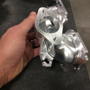
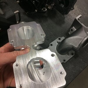
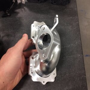
Side note, here's a couple of photos of a manifold that I machined for my 550 a couple of years ago.
 

Attachments

  • B81F8672-8CBC-4082-8B0C-EFC5D964D433.jpg
    B81F8672-8CBC-4082-8B0C-EFC5D964D433.jpg
    141.4 KB · Views: 31
  • 58171F29-C599-4BA4-B69B-8E119C5FAE6E.jpg
    58171F29-C599-4BA4-B69B-8E119C5FAE6E.jpg
    148.8 KB · Views: 31
  • F9DDFD1E-92C9-4B92-AA20-3112548ACAB7.jpg
    F9DDFD1E-92C9-4B92-AA20-3112548ACAB7.jpg
    144.1 KB · Views: 33
Maybe the next time when my motor needs to be bored out, I might think long and hard about pressing the sleeves out, and raising them then, but I'm not to worried about that at the moment.
For what it’s worth, a nice 15 min soak at 450° the sleeves come right out without pressing. Getting them back in is the same but requires a press as well
 
Top Bottom