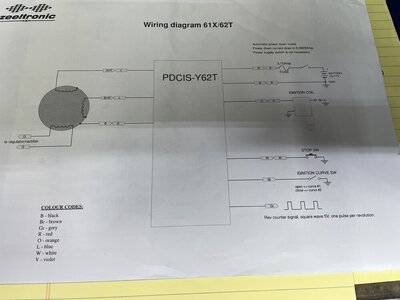
62t zeeltronic installation

hi all, I just got the 62t zeeltronic today and looks like it has more wire than stock cdi it actually comes with wiring diagram but I suck at figuring it out lol. So wondering if anyone can help me with installation guide such as actual picture of which wire go to which I would be very much appreciated. or anything I need to do before installing it because I don't wanna damage it.

thanks in advance
 
the grey wire is tachometer output and the brown is a map switch. both are not needed if you do not wish to use these functions. ( most people do not) you need to add an inline fuse to the red wire to power the zeel. follow the colors on the wiring diagram for the rest of the wires
 
the grey wire is tachometer output and the brown is a map switch. both are not needed if you do not wish to use these functions. ( most people do not) you need to add an inline fuse to the red wire to power the zeel. follow the colors on the wiring diagram for the rest of the wires
hi thank you so kuch for your help. there are 2 red wires attached together which makes me confused since the stock cdi only have one red wire. do I just use one and leve the other one? could you also tell me how to install map switch since there are 3 wires from the switch, brown goes yo brown and ...??
sorry for the dumb question but I really never have experience with this.
thanks in advance sir
 
Location
Seattle
hi thank you so kuch for your help. there are 2 red wires attached together which makes me confused since the stock cdi only have one red wire. do I just use one and leve the other one? could you also tell me how to install map switch since there are 3 wires from the switch, brown goes yo brown and ...??
sorry for the dumb question but I really never have experience with this.
thanks in advance sir
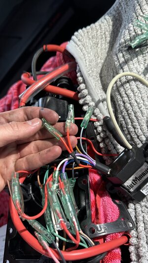
What did you end up doing on this ? For the red wires. I’m at the same spot and confused as well
 
The 2 Red Wires supply Power to the Starter Relay and to the Zeeltronic CDI.

There is one extra Red Wire required because now, the DC Zeel CDI needs DC Power directly from the Battery whereas the Stock AC CDI got AC Power from the Magneto Generator Charging Coil (Brown/White Wire from Flywheel Cover). So the Original Factory E-Box only comes with one Red Wire just for the Start Button to the Starter Relay.

Already have one Red Power Wire with a Split and a 10 Amp Fuse going to the Starter Relay (to energize the Starter) and to the Regulator/Rectifier (to charge the Battery). Connect one Zeel Red Wire to this existing Red Fused Wire.

For the other Zeel Red Wire, you need to supply/build/make-up another Red Wire with a 3 Amp Fuse and connect to the Red Battery Cable at the "Hot" Relay Post fed by the Red Battery Cable. This new Red Wire will provide constant DC Power from the Battery to the Zeel CDI.

So that's the missing piece of the Puzzle...
 
Last edited:
Location
Seattle
The 2 Red Wires supply Power to the Starter Relay and to the Zeeltronic CDI.

There is one extra Red Wire required because now, the DC Zeel CDI needs DC Power directly from the Battery whereas the Stock AC CDI got AC Power from the Magneto Generator Charging Coil (Brown/White Wire from Flywheel Cover). So the Original Factory E-Box only comes with one Red Wire just for the Start Button to the Starter Relay.

Already have one Red Power Wire with a Split and a 10 Amp Fuse going to the Starter Relay (to energize the Starter) and to the Regulator/Rectifier (to charge the Battery). Connect one Zeel Red Wire to this existing Red Fused Wire.

For the other Zeel Red Wire, you need to supply/build/make-up another Red Wire with a 3 Amp Fuse and connect to the Red Battery Cable at the "Hot" Relay Post fed by the Red Battery Cable. This new Red Wire will provide constant DC Power from the Battery to the Zeel CDI.

So that's the missing piece of the Puzzle...
Thank you for your detailed response ! Much appreciated
 

Jr.

Standing Tall
Staff member
Site Supporter
Location
Hot-Lanta
Here is the Y62T wiring diagram. Pretty simple if followed correctly. Make sure you have the fused link attached to the battery side post on solinoid. Once thru fused link, all reds get daisy chained together. Same for all Neg (black) wires. Brown is your curve switch. Open circuit is map 1 , closed (brown to ground) is map 2. The grey wire is tach signal, in most case not used

P


65723861646__8487402B-B07C-451E-BEE3-B94F6FCDC914.jpeg
 
Top Bottom