- Location
- Texas
CALCULATING FLYWHEEL MAGNET STRENGTH
This is a Crude Ballpark attempt at calculating the Flywheel Magnet Strength to use as a reference tool to distinguish a Good Flywheel from a Bad Flywheel. Then the Actual Magnet Strength can be measured with a Gauss Meter and compared to the Nominal Calculated Strength.
Of course, the best Reference Magnet Strength Number would be from an Actual Gauss Meter Reading taken from a Brand New Known Good Flywheel. But we don't all own a collection of various Good Flywheels available for bench measurements. Most typically have one going/gone bad and looking to replace it with another used unknown condition Flywheel...
So far, the following Tests are available:
So here goes an attempt to calculate the approximate Magnet Strength knowing the Voltage generated, the RPMs, the Magnet Surface Area and the Number of Turns in the Coil.
Have the following rough Data for a Yamaha 701 PWC Magneto Generator:
Charging Coil 30-50 VAC @ 600 rpm Cranking Speed
Lighting Coil 6-10 VAC @ 600 rpm Cranking Speed
Pulse Coil 4-5 VAC @ 600 rpm Cranking Speed
Approximate Number of Turns in Charging Coil 2000 Turns of 38 SWG/34AWG Copper Wire (capable of about 600 VAC Output at 6K-7K rpms)
Approximate Flywheel Magnet Area (63M 1100 Flywheel) 4-1/4” Diameter x 1-3/8” Wide (I don't have a 61X or 62T Flywheel on hand)
Calculating Magnet Surface Area: Assuming 4 Magnets, then each would have Area = ¼ of Circumference x Width = 1/4(Pi x D) x W = 1/4(3.14 x 4.25”) x 1.375” = 4.6 sq. in
Converting to Square Meters 4.6 sq. in x (2.54 cm x 2.54 cm) x sq. meter/(100 cm x 100 cm) = 0.003 sq. meters. Because the Formula uses Metric Numbers.
Faraday's Law: Magnet Strength B in Tesla Units = Voltage/(Number Turns x Magnet Area x RPMs in Radians)
Before plugging and chugging, RPMs need to be converted to Radians per Second. So one Revolution = 360 degrees which equals (2 x Pi) Radians, then 1 rev = 2Pi radians.
600 RPM x 60 sec/ min = 10 rev/sec x 2Pi/rev = 63 rad/sec
Now Magnet Strength B for Charging Coil = 50 VAC/(2000 turns x 0.003 sq. meter x 63 rad/sec) = 0.13 Teslas
But a Tesla = 10000 Gauss, so B = .013 T x 10000 Gauss/T = 1322 Gs (roughly)
Maybe it's supposed to be 4 times as much (5288 GS), since used only a 1/4 of the total available Magnet Area.
The same calculations can be done for the Lighting Coil and Pulse Coil, although need to find out the number of turns in each Coil. All three calcs should come out the same.
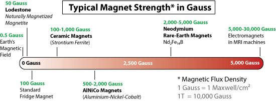
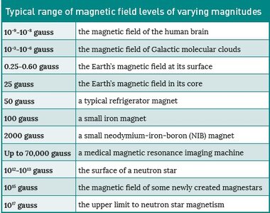
Looking at the Chart, looks like it's in the Ballpark; but how does it compare to an ACTUAL Gauss Meter reading of a Known Good Flywheel?
 Anybody have actual 61X or 62T Flywheel Magnet diameter and width measurements?

This is a Crude Ballpark attempt at calculating the Flywheel Magnet Strength to use as a reference tool to distinguish a Good Flywheel from a Bad Flywheel. Then the Actual Magnet Strength can be measured with a Gauss Meter and compared to the Nominal Calculated Strength.
Of course, the best Reference Magnet Strength Number would be from an Actual Gauss Meter Reading taken from a Brand New Known Good Flywheel. But we don't all own a collection of various Good Flywheels available for bench measurements. Most typically have one going/gone bad and looking to replace it with another used unknown condition Flywheel...
So far, the following Tests are available:
- Voltage Test which involves having the unknown condition Flywheel in question installed in the Engine. Cranking Voltage should be between 30 to 50 VAC. Installed Test.
- Screwdriver Hang Test as a rough Magnet test of Strength. Each Magnet should have about equal Pull Force. Bench Test.
- Resistance Test across Magnet's Poles. Each Magnet should have about the same Resistance reading. Bench Test.
So here goes an attempt to calculate the approximate Magnet Strength knowing the Voltage generated, the RPMs, the Magnet Surface Area and the Number of Turns in the Coil.
Have the following rough Data for a Yamaha 701 PWC Magneto Generator:
Charging Coil 30-50 VAC @ 600 rpm Cranking Speed
Lighting Coil 6-10 VAC @ 600 rpm Cranking Speed
Pulse Coil 4-5 VAC @ 600 rpm Cranking Speed
Approximate Number of Turns in Charging Coil 2000 Turns of 38 SWG/34AWG Copper Wire (capable of about 600 VAC Output at 6K-7K rpms)
Approximate Flywheel Magnet Area (63M 1100 Flywheel) 4-1/4” Diameter x 1-3/8” Wide (I don't have a 61X or 62T Flywheel on hand)
Calculating Magnet Surface Area: Assuming 4 Magnets, then each would have Area = ¼ of Circumference x Width = 1/4(Pi x D) x W = 1/4(3.14 x 4.25”) x 1.375” = 4.6 sq. in
Converting to Square Meters 4.6 sq. in x (2.54 cm x 2.54 cm) x sq. meter/(100 cm x 100 cm) = 0.003 sq. meters. Because the Formula uses Metric Numbers.
Faraday's Law: Magnet Strength B in Tesla Units = Voltage/(Number Turns x Magnet Area x RPMs in Radians)
Before plugging and chugging, RPMs need to be converted to Radians per Second. So one Revolution = 360 degrees which equals (2 x Pi) Radians, then 1 rev = 2Pi radians.
600 RPM x 60 sec/ min = 10 rev/sec x 2Pi/rev = 63 rad/sec
Now Magnet Strength B for Charging Coil = 50 VAC/(2000 turns x 0.003 sq. meter x 63 rad/sec) = 0.13 Teslas
But a Tesla = 10000 Gauss, so B = .013 T x 10000 Gauss/T = 1322 Gs (roughly)
Maybe it's supposed to be 4 times as much (5288 GS), since used only a 1/4 of the total available Magnet Area.
The same calculations can be done for the Lighting Coil and Pulse Coil, although need to find out the number of turns in each Coil. All three calcs should come out the same.
Looking at the Chart, looks like it's in the Ballpark; but how does it compare to an ACTUAL Gauss Meter reading of a Known Good Flywheel?
 Anybody have actual 61X or 62T Flywheel Magnet diameter and width measurements?

Last edited:

