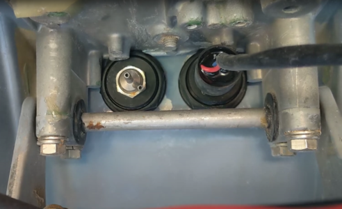
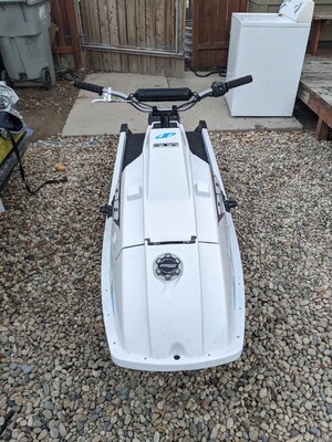
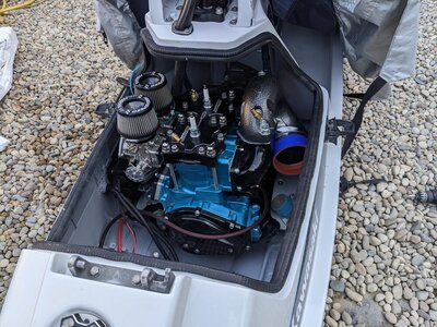
Start to finish project of a Kawasaki X2 converted into a Yamaha 701 61x/62t with a Yamaha 144 pump/shoe/grate.
This build has tubbies, and a frontal exhaust moved to the front, and conversion products from Rhaas Products.

Here's some pictures of the starting ski and the end result before I get into the project in detail.

100% here to answer every question, so please ask them! I really enjoyed this project and it was definitely doable!

Going to put a youtube video of this project in this thread when that gets finished.
 

Attachments

  • PXL_20221030_004023955.jpg
    PXL_20221030_004023955.jpg
    229.4 KB · Views: 74
  • PXL_20221030_004051682.jpg
    PXL_20221030_004051682.jpg
    190.6 KB · Views: 69
  • PXL_20221030_004107851.jpg
    PXL_20221030_004107851.jpg
    232 KB · Views: 62
  • PXL_20221030_004118922.jpg
    PXL_20221030_004118922.jpg
    248.4 KB · Views: 61
  • PXL_20221030_004124954.jpg
    PXL_20221030_004124954.jpg
    222 KB · Views: 76
  • PXL_20221011_231543221.MP.jpg
    PXL_20221011_231543221.MP.jpg
    212.7 KB · Views: 88
  • PXL_20220611_023935335.jpg
    PXL_20220611_023935335.jpg
    203.7 KB · Views: 85
First step was to gut it. I wasnt keeping any of it.
Get rid of the junk steering/ bars too. So literally everything goes. And in this project im also converting the pump, so yes that goes too.

Few things to keep:
-Gas tank. ( i went with a superjet gas tank, but in retrospect using a stock X2 tank would have been SOO much easier.)
-I cut off the brackets that the Fuel pump was attached to and shaved that whole area flat. But I would recommend keeping the two brackets that i circled in blue, and youll be using them later to mount the E-box back onto the frame. Youll glass them back on)
-OEM x2 turn cable.
-gas tank fuel neck.
-oem fuel lines if they are still in good shape.
-oem water lines if they are also in good shape.
-battery box and straps.
-all the bumpers.
-Seat.

Clean it with dawn dish soap, and a scratch pad, and even some engine degreaser.
 

Attachments

  • Screenshot 2022-11-13 001710.png
    Screenshot 2022-11-13 001710.png
    669.9 KB · Views: 82
  • PXL_20220706_012320028.jpg
    PXL_20220706_012320028.jpg
    110.8 KB · Views: 79
Last edited:
Next you'll want to do any type of body repairs.
Products to buy:
-Epoxy , get some from USComposites. they make good stuff.
-Cab-o-sil (also uscomposites)
-TotalFair fairing compound.
-Bondo Spot glazing putty.

First you should sand it smooth. You can use a random orbital sander as long as you dont go over corners and edges with it. It will eat those edges extremely quickly.
Your goal is to keep the stock shape and thickness as much as possible. So do a light sanding.

Then go through and use thickened epoxy (cabosil to make it the consistancy of toothpaste) and fill in big gashes.
If theres any brittle weak points, you should grind it out completely and then glass it back to being structrual.

I use epoxy, cabosil, and pulled apart glass and mix them in a cup to do easy fiberglass repairs.

Then for all other small gashes, and finishing touches, you should use a fairing compound because of how easy it is to sand ( green mixture in pictures)

Last step, is to fill in all the pinholes with Bondo spot putty. It drys in 30 minutes and you just rub it into the pinholes with your fingers.
 

Attachments

  • PXL_20220722_001358851.jpg
    PXL_20220722_001358851.jpg
    166.7 KB · Views: 71
  • Screenshot 2022-11-12 225808.png
    Screenshot 2022-11-12 225808.png
    418.2 KB · Views: 58
  • Screenshot 2022-11-12 225643.png
    Screenshot 2022-11-12 225643.png
    571.3 KB · Views: 55
  • Screenshot 2022-11-12 225512.png
    Screenshot 2022-11-12 225512.png
    503.8 KB · Views: 52
  • Screenshot 2022-11-12 225415.png
    Screenshot 2022-11-12 225415.png
    289.2 KB · Views: 54
  • PXL_20220723_011315730.jpg
    PXL_20220723_011315730.jpg
    150.2 KB · Views: 52
  • PXL_20220722_225317943.jpg
    PXL_20220722_225317943.jpg
    138.6 KB · Views: 56
  • PXL_20220720_000505093.jpg
    PXL_20220720_000505093.jpg
    136.3 KB · Views: 63
Buy some 5200 and cover all the holes that enter into the tray area so that it doesnt water log your ski.
Can potentially put 100lbs of weight in the rear if you dont seal up your ski.
For whatever reason, yamaha or kawasaki dont take the time to cover the foam holes.
What this picture doesnt reflect is that i removed the top hose inlet as well and sealed it up. You only need those two lower ones.
 

Attachments

  • Screenshot 2022-11-12 225150.png
    Screenshot 2022-11-12 225150.png
    510.9 KB · Views: 72
Last edited:
I bought a front gas cover from Glyn Church. Makes an awesome product and its easy to install.
I just took a grinder and cut out that whole area, but left a small lip for the plate to rest onto.
I put some thickened epoxy on that lip then layed down the cover.
I would reccomend raising it as much as you can so that its flush with the hull.
I had to put on a layer of fairing compound and do some sanding on the lower half to get it to level out and look stock.
Then just use a whole saw to cut out for the fuel neck.
I used a yamaha superjet fuel cap.
Id also reccomend swapping to nuts and bolts rather than using the stock self tapping screws. they get lose and spin freely.
 

Attachments

  • Screenshot 2022-11-12 224555.png
    Screenshot 2022-11-12 224555.png
    621.9 KB · Views: 63
  • Screenshot 2022-11-12 233956.png
    Screenshot 2022-11-12 233956.png
    300.5 KB · Views: 55
  • Screenshot 2022-11-12 224920.png
    Screenshot 2022-11-12 224920.png
    758.1 KB · Views: 61
  • Screenshot 2022-11-12 224656.png
    Screenshot 2022-11-12 224656.png
    500.7 KB · Views: 65
  • PXL_20221030_004103287.jpg
    PXL_20221030_004103287.jpg
    148.5 KB · Views: 68
  • Screenshot 2022-11-12 224836.png
    Screenshot 2022-11-12 224836.png
    777.3 KB · Views: 68
Heres an example of the concoction i make when doing epoxy/cabosil/glass strands and just glooping it into repair areas.
So easy, and does awesome work.
Anyone else do this?
Or do you take the time to lay up layers of cut glass matts? and keep adding layers.
 

Attachments

  • Screenshot 2022-11-12 230623.png
    Screenshot 2022-11-12 230623.png
    644.5 KB · Views: 97
From here I'll go into whats needed for the driveshaft conversion.
You will need to buy:
-Waveblaster 3 driveshaft
-GP800 midshaft plate. Its basically a spacer. Its what the midshaft rests on. But its simply a spacer.
-Superjet midshaft housing
-Superjet midshaft.
-Rhaas Products conversion plate.

On the GP800 spacer, youll have to grind off a good chunk of the part that inserts into the PVC pipe area.
If you dont, it will hit the pvc pipe and not push in fully.
Youll want to shave off just enough though, because you dont want any air pockets. So fill in the gap with some 5200.
I attached a screenshot below of how much i took off the tip.

So the tricky part to this was taking apart a superjet pump assembly / shaft and replacing it with a waveblaster shaft.

Heres some tips...
Dont try and save the bearings, just buy some new ones since you more than likely need new ones anyways.
This allows you to just tap them out brutally with a screwdriver and hammer.

From there, do this trick with your new bearings:
-Freeze your drive shaft, so that the drive shaft shrinks. (it does, trust me!!)
-Put your new bearings in the oven for 40 minutes on 300 degrees.
-Take shaft out of freezer and bearings out of oven and the bearings will SLIP ON. If they dont slip on with absolutely zero effort, then they need to bake longer and be in freezer longer.
-once the bearings are on. Pack the soace inbetween both bearings with greace, then freeze that. Then just similar to before, youll put your pump in the oven. Then the bearing/shaft assembly should slip right into your pump assembly with ease... and i mean it literally falls into place.
-BOOM YOURE DONE!! PUMP REBUILD DONE!!!!

When you put on the parts above, make sure you use a sealant between each layer to water proof them.
Youll also want to get this part of the project done so that you can easily allign your new yamaha 144 pump so that its all centered.
 

Attachments

  • Screenshot 2022-11-12 230118.png
    Screenshot 2022-11-12 230118.png
    826 KB · Views: 103
  • PXL_20220923_002956134.jpg
    PXL_20220923_002956134.jpg
    146.5 KB · Views: 101
  • PXL_20220807_224500686.jpg
    PXL_20220807_224500686.jpg
    102 KB · Views: 92
  • PXL_20220807_214057766.jpg
    PXL_20220807_214057766.jpg
    126.5 KB · Views: 87
  • PXL_20220807_201951111.jpg
    PXL_20220807_201951111.jpg
    130.7 KB · Views: 83
  • Screenshot 2022-11-12 230154.png
    Screenshot 2022-11-12 230154.png
    954.6 KB · Views: 90
Last edited:
You may consider flat topping your ski because alternatively you could do what these pictures reflect... but it took alot of hours to do, and it was really tidious....

I used the stock stearing cover and grinded off all the dial / trim areas and glassed them smooth to shape...
Also had to do it to the hull itself.
The end result obviously looks really nice... but i can now see why people just "flat top" the hood and handlepole area. It would have taken literally minutes to make that flat and sand it smooth rather than the hours this little project turned into.

Your choice!
 

Attachments

  • PXL_20221030_004124954.jpg
    PXL_20221030_004124954.jpg
    222 KB · Views: 93
  • Screenshot 2022-11-12 225919.png
    Screenshot 2022-11-12 225919.png
    453.2 KB · Views: 85
  • Screenshot 2022-11-12 225933.png
    Screenshot 2022-11-12 225933.png
    431 KB · Views: 76
  • Screenshot 2022-11-12 232324.png
    Screenshot 2022-11-12 232324.png
    436.4 KB · Views: 75
  • Screenshot 2022-11-13 005821.png
    Screenshot 2022-11-13 005821.png
    905.2 KB · Views: 76
The other project you may also consider NOT doing is this one....
It looks really nice as well, but you need a special equipment that i didnt have.
When I cut the holes, i realised they needed to be just ever so slightly lower.
When i looked inside, i found that the inserts would be hitting up against a metal piece on the inside.
So i had to file that down with a round file, and that took about 30 minutes of just filing those metal pieces down so that the inserts would slide into place.
Then the second issue was getting the washer on the other side to fit.
The trick with that i found was to insert the washer first, then slide the other piece in, and you had to hold the washer in place with your fingers from one side, and simply tighten the other side with the palm of your hand by pushing with your palm and twisting.
BUT.... again.. The end result is AWESOME!! and the placement is beyond conveniant.
 

Attachments

  • Screenshot 2022-11-13 005821.png
    Screenshot 2022-11-13 005821.png
    905.2 KB · Views: 67
  • Screenshot 2022-11-12 234822.png
    Screenshot 2022-11-12 234822.png
    191.4 KB · Views: 67
  • Screenshot 2022-11-12 235235.png
    Screenshot 2022-11-12 235235.png
    617.2 KB · Views: 64
  • Screenshot 2022-11-12 234933.png
    Screenshot 2022-11-12 234933.png
    363.8 KB · Views: 72
  • Screenshot 2022-11-12 234948.png
    Screenshot 2022-11-12 234948.png
    680.7 KB · Views: 75
Heres a picture of where i glassed into place the mounts that i retained from the stock oem pump bracket that i initially grinded off.
If you are mounting your EBOX in the same place I did, if you can see by my picture attached, you should shift it to the right just a half an inch.
Basically directly to the left of the rib.
Mine started about an inch to the left of the rib, and it barely grazed my battery box, so it would have been better a bit further to the right to start the ebox mount.
but the height was good.
If you need to project the ebox futher outward , like i ended up needing, i used a silicone spacer which i also will be using and demonstrating that spacer used later on in this thread.

But this location ended up being awesome!! REALLY happy with the way it turned out.
Lots of room in that specific location and doesnt interfere with carb tuning in any way.
 

Attachments

  • Screenshot 2022-11-12 235126.png
    Screenshot 2022-11-12 235126.png
    636.3 KB · Views: 77
  • PXL_20220930_213205582.jpg
    PXL_20220930_213205582.jpg
    156 KB · Views: 82
  • PXL_20221011_231543221.MP.jpg
    PXL_20221011_231543221.MP.jpg
    212.7 KB · Views: 81
This is the Rhaas Products engine conversion brackets youll need to buy.
Comes with the engine mounts.

You will want to follow the instructions.
When you are grinding out the battery box area, make sure to grind out as low as you can go in that corner they have you grind out.
Also, what i didnt notice in the instructions until i was putting it together, was that you also need to grind out some of the areas where the screws go through the holes as it will bump into some of the ribs.
 

Attachments

  • PXL_20220923_002956134.jpg
    PXL_20220923_002956134.jpg
    146.5 KB · Views: 74
  • Screenshot 2022-11-12 232214.png
    Screenshot 2022-11-12 232214.png
    490.6 KB · Views: 69
  • Screenshot 2022-11-12 232421.png
    Screenshot 2022-11-12 232421.png
    554.4 KB · Views: 65
  • Screenshot 2022-11-12 232442.png
    Screenshot 2022-11-12 232442.png
    504.1 KB · Views: 77
Sweet build man work looks great and good write up. It's almost as much work typing it all up and taking, organizing pics as it is doing the work haha. I'm still curious how the pump conversion works but you'll definitely clear that up. Keep it up
 
Onto the Pump area.

First, you should have your WB3 driveline assembled to the Superjet 144 pump already.
-Then go ahead and slip your aluminum shoe into place. It should be even with where your water lines / turn cable come out.
-As you can see in my attached picture, i would recommend grinding off your shoe along the lines i drew on my shoe. That way they dont bump against your trim/bilge/turn cable.
-Youll also need to grind out slits into the rear pump mount latches. as shown in the picture attached. They will be somewhat at an angle.
-Youll then need to drill through hull to the oher side of the seat latch area to make holes for your rear pump mounts. You'll grind through literally touching the seat bracket, so I had to grind out a notch in my seat latch to make room for a bolt and washer.
-I also used some 30mm nylon washers i bought off amazon. as shown in the picture. And they worked out perfectly to raise the back pump bolts up perfectly.
-Your goal is to raise up the rear so that the driveshaft is perfectly centered in the PVC pipe.
-The two holes should be perfectly mirrored on each side.
-You can always add more nylon washers or stainless steal washers to raise the back up further.
-Once you find the perfect amount of nylon washers to create the perfect height, youll want to take this all out and get ready to epoxy in the shoe while attached to the whole pump assembly while it dries.
 

Attachments

  • PXL_20220810_225506047.jpg
    PXL_20220810_225506047.jpg
    115.1 KB · Views: 83
  • Screenshot 2022-11-12 225327 - Copy.png
    Screenshot 2022-11-12 225327 - Copy.png
    719.1 KB · Views: 82
  • Screenshot 2022-11-12 230426.png
    Screenshot 2022-11-12 230426.png
    476.4 KB · Views: 77
  • Screenshot 2022-11-12 230507.png
    Screenshot 2022-11-12 230507.png
    650.8 KB · Views: 83
I did this mostly by eyeballing it, and feeling it.
Heres just a cluster of tips for this part of this project:
-Use a clamp to keep the entire assembly together with all parts centered.
-While centering everything, put all 4 pump bolts into place as well as the nylons that will raise it the correct distance.
-Make some marker notches on the hull and pump to know where everything is alligned.
-Your ONLY goal is to make sure the shoe is even height on the left and right and then also centered by seeing where the driveshaft is in the PVC pipe.
-Shoe should not be at an angle, but instead perfectly verticle.
-The inside of the shoe should be identical to the pump circle.
-Take the entire pump assembly off, then apply a layer of thickened epoxy around the entire area the shoe will be. Use a decent amount of thickened epoxy and let it squeeze out.
-Take your time centering it at this point. then clean up all the edges. THEN DONT TOUCH IT for 24 hours.
-remove the pump assembly and you are left with the shoe attached.
-At this point, start filling in all the missed areas with more thickened epoxy.
-Then you will spend alot of time blending in the pump area with TotalFair to make it have a good hydrodynamic drag into the pump.
-Lots of sanding with the palm of your hand with big strides.
 

Attachments

  • Screenshot 2022-11-12 231242 - Copy.png
    Screenshot 2022-11-12 231242 - Copy.png
    607.3 KB · Views: 84
  • Screenshot 2022-11-12 231218 - Copy.png
    Screenshot 2022-11-12 231218 - Copy.png
    516.9 KB · Views: 91
  • Screenshot 2022-11-12 231147.png
    Screenshot 2022-11-12 231147.png
    535.6 KB · Views: 83
  • Screenshot 2022-11-12 231019 - Copy.png
    Screenshot 2022-11-12 231019 - Copy.png
    577.6 KB · Views: 90
  • Screenshot 2022-11-12 230828.png
    Screenshot 2022-11-12 230828.png
    532.1 KB · Views: 85
  • Screenshot 2022-11-12 230654 - Copy.png
    Screenshot 2022-11-12 230654 - Copy.png
    548.8 KB · Views: 83
  • Screenshot 2022-11-12 230906 - Copy.png
    Screenshot 2022-11-12 230906 - Copy.png
    567.5 KB · Views: 92
Heres the finished product of pump assembly area
 

Attachments

  • PXL_20220821_211523122.jpg
    PXL_20220821_211523122.jpg
    108.2 KB · Views: 92
  • PXL_20220822_011541952.MP.jpg
    PXL_20220822_011541952.MP.jpg
    146.8 KB · Views: 85
  • PXL_20220822_011608040.jpg
    PXL_20220822_011608040.jpg
    42.8 KB · Views: 79
  • PXL_20220824_001901446.jpg
    PXL_20220824_001901446.jpg
    156.2 KB · Views: 76
  • Screenshot 2022-11-12 231716.png
    Screenshot 2022-11-12 231716.png
    414.4 KB · Views: 75
  • Screenshot 2022-11-12 231739.png
    Screenshot 2022-11-12 231739.png
    584.9 KB · Views: 72
  • Screenshot 2022-11-12 231922.png
    Screenshot 2022-11-12 231922.png
    616.9 KB · Views: 73
Added the pump stuffer. I could have just glassed something similar, but i had one purchased already so i planned on using it.
Easy to install with the driveshaft out. Just use a bead of silicone.
 

Attachments

  • Screenshot 2022-11-12 231904.png
    Screenshot 2022-11-12 231904.png
    809.6 KB · Views: 71
  • Screenshot 2022-11-12 231922.png
    Screenshot 2022-11-12 231922.png
    616.9 KB · Views: 67
Painted my ski.
Also i cut my seat foam off in the front. It didnt look very good with the fact that i removed the plastic dial cover that was purple.
Then covered it with a new seat cover.
So instead ill be turfing the front area.
 

Attachments

  • Screenshot 2022-11-12 234041.png
    Screenshot 2022-11-12 234041.png
    866.8 KB · Views: 66
  • Screenshot 2022-11-12 234057.png
    Screenshot 2022-11-12 234057.png
    826.8 KB · Views: 65
Next on the list was to add the exhaust outlet.
Purchased from Rhaas Products.
I thought i put it pretty far forward, but little did I know I needed to slam it as FAR FORWARD AS HUMINLY possible.
Even to the point where the metal hinge might be slightly past the hull.
You also want it as high as possible. That way the Tubbies are in the correct position.

Reason being; you want whatever waterbox you choose to be shifted as far back as possible.
I ran into some issues using a SeaDoo HX waterbox, but i made it work, and ill go over that later in this post.

I used the "inside" outlet to draw an outline of where ill need to make a cut with my circular saw.
I then used 5200 to coat the inside seams to protect everything from heat and wear.
 

Attachments

  • Screenshot 2022-11-12 233008.png
    Screenshot 2022-11-12 233008.png
    654.4 KB · Views: 58
  • Screenshot 2022-11-12 233740.png
    Screenshot 2022-11-12 233740.png
    1,003 KB · Views: 54
  • Screenshot 2022-11-12 233804.png
    Screenshot 2022-11-12 233804.png
    514.5 KB · Views: 64
Top Bottom