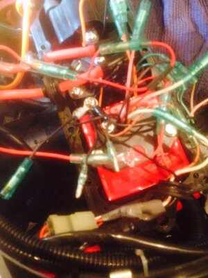
MSD enhancer installation

Can anyone provide a picture of their current wiring diagram scheme? I have two male connectors which are not connected to anything at the moment. one is from the stator and the other is from the start stop switch. One end is from the MSD black eyelet and female end connector that connects to the thermo switch that I will not be running so I will just tape up as per the instructions.

 

Attachments

  • FullSizeRender-6.jpg
    FullSizeRender-6.jpg
    140.4 KB · Views: 160

mike b

Michael "Mayhem" Bevacqua aka MikeyChan
Location
California
Are they all black wires and a pink? If so i had a similar thing. I believe I was able to connect all the blacks together except for one. I taped up the black and pink separately and put them in the ebox. Few plastic ties and it cleaned up a bit
 
sorry I believe that I would have to leave the one pink cable free and one black male cable from the engine stop switch (two green wires, one white/red, and one white/brown) rather than the start stop switch
 

OCD Solutions

Original, Clean and Dependable Solutions
Location
Rentz, GA
The black wire from the start/stop and the black wire from the stator harness MUST be connected with all the other blacks!!!
 

OCD Solutions

Original, Clean and Dependable Solutions
Location
Rentz, GA
Doesn't matter. Black is black. Just make sure that the black from each component is somehow connected back to the ground post.
 

mike b

Michael "Mayhem" Bevacqua aka MikeyChan
Location
California
@OCD Solutions I believe there is a male end from the MSD that is mated off of the grounding wire that is screwed into the box. Can't this one stay free if there is not a female connector available since this wire still goes to the ground? Everything is grounded at the point already
 
Doesn't matter. Black is black. Just make sure that the black from each component is somehow connected back to the ground post.

Yes all black eyelet wires are leading back to the ground post, but I have 3 wires which have black wires as return, two are male connections and one is female, I am unsure which of the male/female wire should be connected together is what I am getting at. No matter what I do I will be left with one free back wire and one free pink wire. I just want to know which should be the free black wire ( male connection) that I should leave unconnected
 

mike b

Michael "Mayhem" Bevacqua aka MikeyChan
Location
California
Yep mine is stock box and just put in an MSD. I thought it was odd too having two wires that don't plug in but one is from the temp guage and the other i found from the CDI itself. I wont be back for a week otherwise id take a picture. I looked at the diagrams on here many times but always had an extra black and pink
 

OCD Solutions

Original, Clean and Dependable Solutions
Location
Rentz, GA
Looks like the black wire with the male end that is connected to the stator harness is the one you leave open. The stator I grabbed to mock it up had this wire taped up already.

That's what you said earlier but I forgot that wire had two connections crimped to the same terminal. When I read it, it sounded like you wanted to leave the stator black disconnected, not the "extra" wire. My bad.
 
Bone stock superjet box? Let me mock it up quick and make sure I'm not missing anything.


she's a 2013 bone stock. Just put some v force reeds in it. Ok so let me break this down as simply as I can. There are two wires that have black wires one is going to the engine stop switch and the other I believe is going to the stop switch per the ignition wiring diagram, items # 4 and 5. The stop switch (wire #1) has one red, brown, white, and black eyelet with male connector return and the engine stop switch (wire #2) has white/red, 2 greens, white/brown, and black eyelet with male connector return. Then the other black wire is the one from the MSD enhance which is black eyelet with female connector. I am unsure of which male end connector should connect to this female connection. My guess is that the black female connection should be connect to the black male connection going to wire #1. The black male connection from wire #2 would be the one for the thermo switch as these wires are the ones that are leading to the engine near the fly wheel cover. The pink wire would also be for the thermo switch?


Any thoughts?
 
Looks like the black wire with the male end that is connected to the stator harness is the one you leave open. The stator I grabbed to mock it up had this wire taped up already.

That's what you said earlier but I forgot that wire had two connections crimped to the same terminal. When I read it, it sounded like you wanted to leave the stator black disconnected, not the "extra" wire. My bad.


thank you.
 
Yep mine is stock box and just put in an MSD. I thought it was odd too having two wires that don't plug in but one is from the temp guage and the other i found from the CDI itself. I wont be back for a week otherwise id take a picture. I looked at the diagrams on here many times but always had an extra black and pink


Yeah the wiring diagram is terrible.
 

OCD Solutions

Original, Clean and Dependable Solutions
Location
Rentz, GA
Well all the critical components and harnesses are terminated with eyelets so the bullet connectors are just for peripherals like the temp switch and Ignition coil.

The black wire from the ignition coil should go the black on the CDI paired with the orange wire. After that point, it's just a matter of connecting the remaining blacks together in whatever configuration makes sense to you.

The schematic is fine, it doesn't go into more detail because it's really not needed.
 
Alright sounds good thanks for the help everyone! I would simply test it out right now, but my head is removed I am waiting for my new one to some in along with a factory b pipe that is apparently on back order till the end of may :(. I will update if I have any issues.
 

OCD Solutions

Original, Clean and Dependable Solutions
Location
Rentz, GA
Too late for you but here's a couple references that may have made things clearer.
 

Attachments

  • Yamaha Electrical Circuit.pdf
    286.8 KB · Views: 135
  • Yamaha MSD Enhancer Wiring.pdf
    21.2 KB · Views: 152
Sorry to revive this old thread but I am running into the same issue. I have a MSD and the rest is stock. I have all wires hooked up BESIDES the male end on my stator connectors. Where does this male need to go. (I have my start stop male going to the MSD if you need to know that..)
 
Top Bottom