F
Freestyleriverrat
Guest
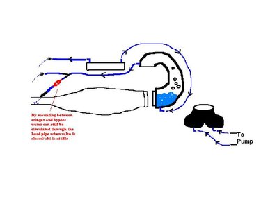
Here is anouther hot topic for the tech section. Below is a pic of how I think I am going to route my cooling lines. In theroy don't you want the flow control valve before the bypass? The bypass lowers line pressure which you need to open the flow control valve. Let me know what you think. I also included a blank pic for you guys to sketch on to illustrate other routing options. I titled the pic below "true" dual cooling b/c both lines go into the exhaust manifold, not one to the manifold and anouther to the head pipe. Please add any coments, considerations and pics so there can be a nice well rounded thread on this issue.
**Also included is a diagram of how my pump area is set up for dual cooling.
**Also included is a diagram of how my pump area is set up for dual cooling.
Attachments


Last edited by a moderator:
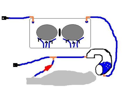
") I was mainly focused on the water to the stinger. That makes sense.....so it should be along the lines of this:
I was mainly focused on the water to the stinger. That makes sense.....so it should be along the lines of this: