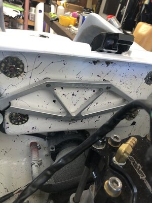
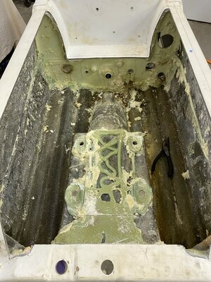
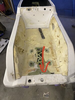
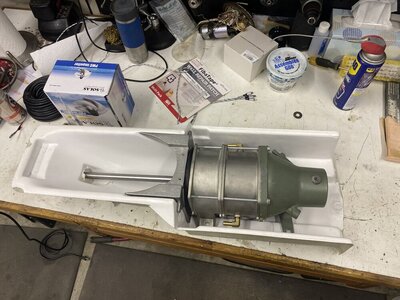
NW FX1 Build w/TOM 21 144 pump tunnel swap.

Hey Everyone! I'm in the process of acquiring parts and information for my build. I have an Fx1 i bought last year and i love it. I added an fx1 Bpipe, msd enhancer, open air flame arrestor, skat trak 20/27 with a kick, a wolf pump cone, and a quadra fin ride plate. I love it.

I had a chance to ride a fx1 with a ported 760 w/single 46 or 48 novi carb, high compression head (runs pump gas). It also has a 144 pump and the thing ripped.

I came to the conclusion that I wanted more power and thrust and that I wanted to do a pump swap,widened tray, and build a 760 engine. I ride rivers, chase boat wake, and am wanting to ocean ride.

I currently have for my engine: FEEDBACK AND INPUT APPRECIATED
Fx1 bpipe
Programmed zeel for for 760 model PDCIS-A02t
Ported 760 cylinders
the option of running 64x, or 62t cases
Ada head w/40cc domes for 760
Lightened 64x flywheel
760 ebox, stator, and flywheel cover.
I have dual a set of dual sbn 44s, and dual sbn 38s, although I was thinking about running dual 46mm.
I believe I want to buy an rrp internal fill, or superjet fuel tank for the extra capacity

For the hull I'm adding tom 21 sponsons and installing his pump tunnel. I could use advice on what I need to install the pump shoe i.e. Hardware, adhesive/sealant, etc. Could also use any advice and or recommendations period on this process.

I realize there are several posts about the tom21 pump tunnel and pump swap, I've looked at @brapperdoodle and @Sanoman thread pretty extensively. Could also use advice and recommendations here for pump tunnel installation, and widened tray. Would like to know what people wish they would have done differently or added etc.

I've been racking my brain the past few weeks on how to move forward as far as my engine is concerned, as well as my build. Thanks for Looking!2BE78580-C5AB-47C7-99FC-CAFEDD55E3EF.jpeg0C6E71DA-C90C-49F2-9A6C-1C244AE8D164.jpegD3C9D5BA-F1A2-4B84-8348-F1361F65F429.jpeg
 
Last edited:
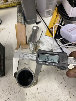
1 thing that is not obvious when swapping to a 144 pump tunnel, is that it can be placed in 2 positions. If you line up the intake grate holes on the pump tunnel with the FX-1 pump tunnel, you will notice the 144 pump tunnel is longer (the pump shoe is further back). I believe it is almost exactly 2 inches. You can either set the pump tunnel in this position, where the tunnel starts in the same place the FX-1 tunnel starts and the pump shoe sits 2" further back OR you can move the tunnel forward and have the pump shoe in the same place as the FX-1 pump shoe. Depending on which you choose, you will either need to run a Superjet driveshaft for the 2" further back OR run an FX-1 driveshaft for the tunnel further forward. I personally decided to align the intake grate holes and have the pump 2" further back than the stock one. Running the pump in this position will make the ski handle more like an aftermarket ski where the pump "sticks out" of the back of the hull. This means more leverage being applied to the rear of the ski when you are turning under thrust, and will throw the rear of the ski more easily when turning.

Aligning the 144 pump shoe area with the FX-1 pump shoe will keep the pump in the same position as the stock one, and the ski will handle more like a regular FX-1. At least that's what I was told haha I haven't actually finished my build yet... getting close though!

P.S. 1 thing I should have done was lower my exhaust tube, it makes the wide tray much easier to finish!
 
Location
dfw
Unless you are pigeon toed, I would make slots at the bottom of the gunwales instead of widening them all the way up. Your engine sounds fine, I would use the 44s and spend time on adjusting the pump load. You said your cylinder is "ported"? That by itself means absolutely nothing without knowing the actual dimensions. Major fiberglass work like this requires a lot of careful fitting in order to make it right so take your time. Using a Superjet driveshaft is best otherwise you will have to cut into the bulkhead in order to get a good inlet radius.
 
Last edited:
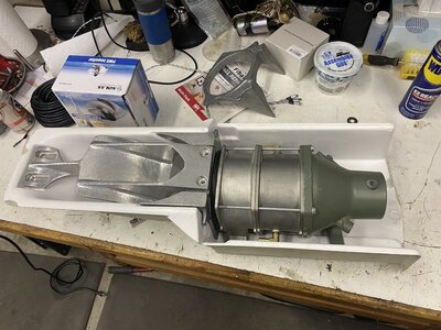
1 thing that is not obvious when swapping to a 144 pump tunnel, is that it can be placed in 2 positions. If you line up the intake grate holes on the pump tunnel with the FX-1 pump tunnel, you will notice the 144 pump tunnel is longer (the pump shoe is further back). I believe it is almost exactly 2 inches. You can either set the pump tunnel in this position, where the tunnel starts in the same place the FX-1 tunnel starts and the pump shoe sits 2" further back OR you can move the tunnel forward and have the pump shoe in the same place as the FX-1 pump shoe. Depending on which you choose, you will either need to run a Superjet driveshaft for the 2" further back OR run an FX-1 driveshaft for the tunnel further forward. I personally decided to align the intake grate holes and have the pump 2" further back than the stock one. Running the pump in this position will make the ski handle more like an aftermarket ski where the pump "sticks out" of the back of the hull. This means more leverage being applied to the rear of the ski when you are turning under thrust, and will throw the rear of the ski more easily when turning.

Aligning the 144 pump shoe area with the FX-1 pump shoe will keep the pump in the same position as the stock one, and the ski will handle more like a regular FX-1. At least that's what I was told haha I haven't actually finished my build yet... getting close though!

P.S. 1 thing I should have done was lower my exhaust tube, it makes the wide tray much easier to finish!
Thanks for the input. I think I'm going to go with the 2 inch setback for the reason of the sj driveshaft, and it seems like most people do.

I was wondering why some people lower their exhaust. Then I saw your post. Do you know why people change out their exhaust tube?
 
Unless you are pigeon toed, I would make slots at the bottom of the gunwales instead of widening them all the way up. Your engine sounds fine, I would use the 44s and spend time on adjusting the pump load. You said your cylinder is "ported"? That by itself means absolutely nothing without knowing the actual dimensions. Major fiberglass work like this requires a lot of careful fitting in order to make it right so take your time. Using a Superjet driveshaft is best otherwise you will have to cut into the bulkhead in order to get a good inlet radius.
thanks for the input. I'll try to get more info on the porting because it was outsourced.

I like the idea of slots for the gunwales.
 
Thanks for the input. I think I'm going to go with the 2 inch setback for the reason of the sj driveshaft, and it seems like most people do.

I was wondering why some people lower their exhaust. Then I saw your post. Do you know why people change out their exhaust tube?

Stock FX-1 and SN exhaust tube is smaller than the RN or any aftermarket stuff. Most everyone runs a 2.5" exhaust tube although the RN tube is 2 3/8" I honestly think its a preference thing but if you're ever going to run a built engine or something with larger displacement you would benefit from the larger exhaust tube, also bumping up to 1/2" cooling lines. You can easily reduce them inside the engine bay to a 3/8" cooling line if you are running a 701, that's what I did.
 

Sanoman

AbouttoKrash
Location
NE Tenn
What brappadoodle said.Always install 1/2” water lines and l like installing a 5/8” trim tube.And think 5 steps ahead! I still make that mistake at times. Did that on my fx1 build.I always like using a cold fusion ebox bracket to be able to remove the ebox without have to go through the turf on the outside of bulkhead in the tray.Great idea (l thought) but now the bpipe head pipe is super close to the bolt on the CF bracket making it a pain in the azz to remove the ebox
 

Attachments

  • 9EF3861C-5BFF-484B-859A-41861C52C977.jpeg
    9EF3861C-5BFF-484B-859A-41861C52C977.jpeg
    131.9 KB · Views: 54
Last edited:
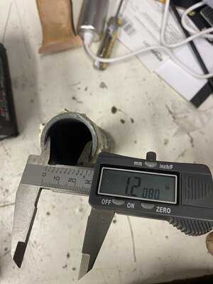
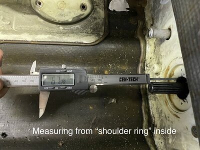
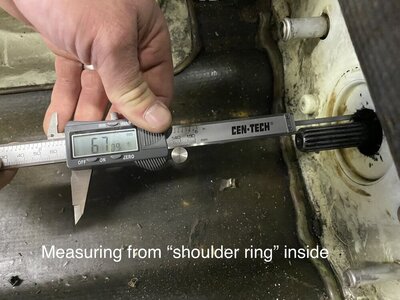
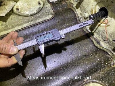
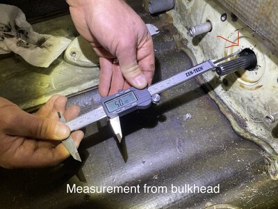
Thanks for all of the help fellas. I'm starting to make some progress. Before removing my stock pump I tried to get some some measurements from the drive shaft tip to the bulkhead (shown in pics). So that when install the tom21 tunnel and pump with pre 08 sj drive shaft I can make sure I'm glassing everything into the proper place. However I'm going to remount my pump and get a measurement with cold fusion alignment tool installed. It makes more sense to do it this way because I can align the pump and set driveshaft to the correct depth simultaneously. There are two different measurements I took. One from bulkhead, and the second from what I call the shoulder ring area inside the bulkhead. Measurements are in Millimeters.
 

Attachments

  • IMG_4692.jpg
    IMG_4692.jpg
    151.9 KB · Views: 40
  • IMG_4693.jpg
    IMG_4693.jpg
    141.8 KB · Views: 35
  • IMG_4695.jpg
    IMG_4695.jpg
    206.5 KB · Views: 32
  • IMG_4696.jpg
    IMG_4696.jpg
    192 KB · Views: 36
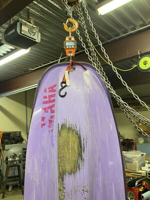
Bare hull no pole. Just stock wear ring, and a Jet Dynamics intake grate which weighed 1.6 lbs.

This was before I cut open my tray and removed foam. I had perhaps a cup of water in my hull when removing foam. But foam itself did not seem to be water logged.

Id say 85lbs give or take is accurate.
 

Attachments

  • weight.jpg
    weight.jpg
    179.1 KB · Views: 42
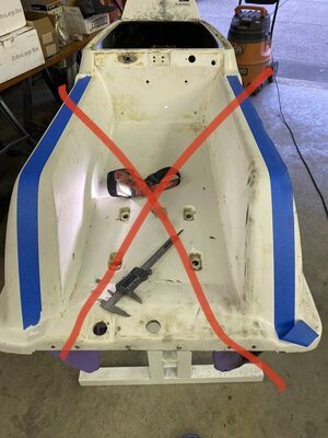
After giving it some though. I decided to mock up my tray with tape. However I didn't like the line I was getting. So I used a straight edge with pencil instead pretty happy with the result. @brapperdoodle had recommended I cut back about 2.5 inches from the front panel. I decided to go with 3" for good measure from bottom and 3.5 towards the top
I figured I can remove more later if needed


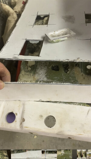
I tried to cut the rear part of my tray extremely shallow to not cut into the bottom mold and removed the bottom half of my tray in two pieces and cut out the brass insert slots which I pried out later. I found a flat pry bar works great for this as well as removal of the foam.

I want a wide tray. But also wanted foot holds. I'm thinking about running rrp removable/adjustable footholds system. Anyone have thoughts on this?
 

Attachments

  • IMG_4774.jpg
    IMG_4774.jpg
    130.3 KB · Views: 43
  • IMG_4912.jpg
    IMG_4912.jpg
    79.6 KB · Views: 36
  • IMG_4883.jpg
    IMG_4883.jpg
    219.9 KB · Views: 34
  • IMG_4880.jpg
    IMG_4880.jpg
    236.7 KB · Views: 35
  • IMG_4855.jpg
    IMG_4855.jpg
    176 KB · Views: 36
  • IMG_4830.jpg
    IMG_4830.jpg
    142.2 KB · Views: 33
So with cold fusion alignment tool instead and measuring from the step of the tip of the caliper seated against the cold fusion plates edge where the slide runs into. FYI if your caliper doesn’t have a stepped tip, the tip of my caliper is 3mm to the step.


Also for reference cold fusion tool is flat and sits flush with firewall. It has also been torqued to fx1 midshaft specs.

My tool was 12.50mm thick.


Now to start trimming the tunnel out.0DF6D83F-2643-448F-A76A-5317112B4BC2.jpegD0906627-DA60-4898-92E5-727B12959C7F.jpeg30606A63-E666-4A1B-80BE-75BFC9D55F17.jpegBE8F1CF8-1EF4-4A6D-B718-E19C15CE015C.jpegDE509E12-C4E5-4984-9980-B0AE2D78DAAE.jpegF93DA7E8-2391-4B07-858E-5A7B3F3AA7CE.jpegEB0A7C56-FE7F-41A0-A4DD-CA070E0C568B.jpeg
 

Attachments

  • IMG_6427.jpeg
    IMG_6427.jpeg
    145 KB · Views: 22
Last edited:
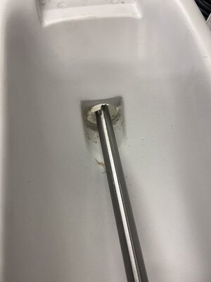
Scratching my head a bit here. Was thinking about mounting my pump to my tunnel to align it that way. My thought is that I can get it into the perfect shaft Alignment position as well as correct depth in the engine bay towards the PTO So 34 mm as shown in previous post from cold fusion alignment tool. For those who don't know I'm running a pre 08 SJ Drive Shaft.
 

Attachments

  • 719DFE2B-D54F-4E25-A2FE-A18038C4C064.jpeg
    719DFE2B-D54F-4E25-A2FE-A18038C4C064.jpeg
    158.7 KB · Views: 40
  • 148F9344-5E10-491A-925A-CE9E640BC659.jpeg
    148F9344-5E10-491A-925A-CE9E640BC659.jpeg
    77.4 KB · Views: 34
  • 4ACA7D14-B025-4E49-9826-3C0DC971A4F3.jpeg
    4ACA7D14-B025-4E49-9826-3C0DC971A4F3.jpeg
    124.7 KB · Views: 36
  • E5A7B974-2962-41AD-BC3A-D5F47E4A09E0.jpeg
    E5A7B974-2962-41AD-BC3A-D5F47E4A09E0.jpeg
    173.1 KB · Views: 40
  • B210EA53-304D-4B65-B355-389FDAB033DC.jpeg
    B210EA53-304D-4B65-B355-389FDAB033DC.jpeg
    97.3 KB · Views: 40
  • 689C12EE-666F-49C3-9E1A-802A0EAD6A07.jpeg
    689C12EE-666F-49C3-9E1A-802A0EAD6A07.jpeg
    54.3 KB · Views: 45

Sanoman

AbouttoKrash
Location
NE Tenn
When l bought mine the tunnel was already installed and didn’t see the need to take it back off (wish l had).Just had to grind most of where they were joined together because there was just resin and no cloth and chopped glass to reinforce it.I really overdid the inside of the tray with a lot of 5 oz glass tweed, but she won’t ever break apart.

You are doing great Drew!
 
Yeah looking great! I reinforced the crap out of mine after using just thickened epoxy and chopped strand to initially set the tunnel. I think I used a little bit of glass on the intake grate area and rear tray area to keep it from dropping down when cured. Defiantly install the pump while epoxying the tunnel into place, I had mine set in place with the cold fusion tool and had it aligned and then gently dumped epoxy around it. I had put some paper or cardboard underneath to catch the extra epoxy that dripped through, which wasn't much because it should be nice and thick. You can drill 3/8" holes and use some cheap hardware to bolt the pump to the tunnel. I also did mine with the hull laying on the ground, on foam pads. Probably many ways to do it but that worked for me and I knew it wasn't gong to move.
 
Here's what mine looked like when I did the rrp footholds in mine. I really like the rrp ninja footholds but I ride with both feet back and most people ride surf stance and dislike them because they take up a lot of space. I have more pictures of them finished but cannot find them at the moment.20190602_121516.jpg20190620_102532.jpg
 
Top Bottom