superjet cdi modification

#ZERO

Beach Bum
Location
Florida - U.S.A.
The stock CDI is not programmable. The curve is generated with an analog circuit, it can't be reprogrammed.

If you want programmable, look into MSD TL, Advent, or the WAX Racing CDI.

Why do you think the ignition timing curve can't be altered?

There's not a single microchip inside a CDI box?

It took me two weeks having the box in an acid tank to dissolve the epoxy & white rock mixture and you're telling me that it can't be changed?
 

Matt_E

steals hub caps from cars
Site Supporter
Location
at peace
Having a microchip doesn't mean it is programmable.

I suspect the curve is generated by some form of analog OpAmp circuit, rather than a PIC with an actual program (discrete), for cost reasons.

OpAmps are Microchips, too, but analog and not programmable.*
Even if the signals are generated via a digital circuit and program, Yamaha would have had zero reason to make it alterable.

I'd love to be wrong on this.
If you post pictures of the CDI circuitry, I'll try to help you out on this.
I know a thing or two about electronics.


*Yes, the circuit behavior can be changed, but it would involve complex circuit analysis and calculation.
 
Last edited:

keefer

T1
Location
Tennessee
From looking at the circuit board I don't see any pin configuration or component top that looks like any IC I am familiar with. Looks like all discrete analog components to me. I would guess a mixture of oscillators and RC tank circuits, I would like to draw up the circuit, but I never have completely got around to removing the potting compound. Interesting what #.0 said about being able to remove the compound by dipping it in an acid bath. I would have thought that it would destroy the components as well. What type of bath did you use to just attack the potting compounds?
 

#ZERO

Beach Bum
Location
Florida - U.S.A.
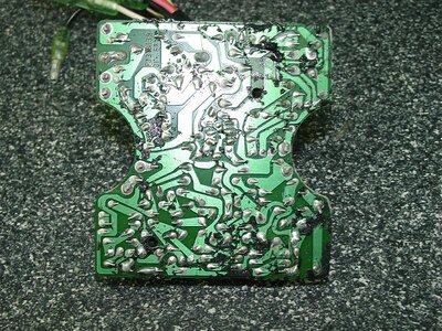
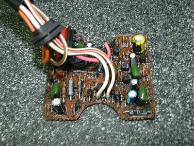
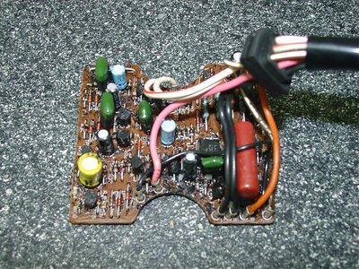
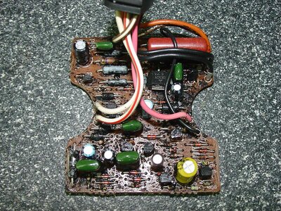
The CDI is composed mostly of resistors & diodes with a few capacitors & transistors.

It doesn't look like it would be that hard to figure out the circuit but I'm working on other projects right now.

I'm sure the timing curve and retard rate could be altered just by installing some trimpots in the right spot.

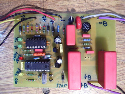
Here are a few pictures of the late model CDI from a superjet, after the epoxy mixture is removed.
 

Attachments

  • Picture 170.jpg
    Picture 170.jpg
    164.8 KB · Views: 974
  • Picture 172.jpg
    Picture 172.jpg
    160.8 KB · Views: 989
  • Picture 173.jpg
    Picture 173.jpg
    155.4 KB · Views: 933
  • Picture 174.jpg
    Picture 174.jpg
    187.5 KB · Views: 945

#ZERO

Beach Bum
Location
Florida - U.S.A.
From looking at the circuit board I don't see any pin configuration or component top that looks like any IC I am familiar with. Looks like all discrete analog components to me. I would guess a mixture of oscillators and RC tank circuits, I would like to draw up the circuit, but I never have completely got around to removing the potting compound. Interesting what #.0 said about being able to remove the compound by dipping it in an acid bath. I would have thought that it would destroy the components as well. What type of bath did you use to just attack the potting compounds?

I had perfectly running CDI box dipped in a carburetor chemical tank for two weeks. The epoxy potting compound had a bunch of white rocks mixed underneath making the job even more difficult. I was able to remove most of the epoxy without destroying the any of the markings on the electronic components.

It would be nice if someone had a schematic of the circuit because it would make modifying the box or making a new CDI a lot easier.

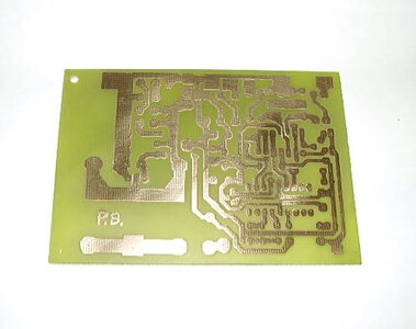
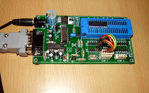
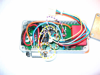
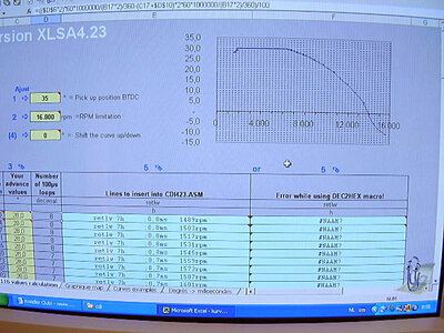
I did some research a while ago and found another site with a custom made CDI that very similar to the superjet box. It would be nice just to start from scratch and make a unit that would be completely programmable similar to the Vilder ignition box.
 

Attachments

  • CDI Box.jpg
    CDI Box.jpg
    123.2 KB · Views: 786
  • CDI PC.jpg
    CDI PC.jpg
    56 KB · Views: 654
  • IC Programmer.jpg
    IC Programmer.jpg
    129.4 KB · Views: 700
  • Test Box.jpg
    Test Box.jpg
    127.6 KB · Views: 696
  • CDI Program.jpg
    CDI Program.jpg
    151.2 KB · Views: 758

Matt_E

steals hub caps from cars
Site Supporter
Location
at peace
From the looks of the components, it's a standard capacitive discharge ignition circuit. There isn't much to it. The diodes and big capacitors serve that circuitry.
I have a diagram for that.

But you would be interested in the timing alteration circuit, not the CDI. Any changes you make to this analog circuitry will have an effect throughout the entire RPM range.
Without thorough circuit analysis and modeling, it will be impossible to predict what changes you'll be effecting by adding trimpots.
I don't see any opamps on the board (but some transistors). The timing is likely to be influenced by a cap or an inductor, not a resistor (though it's possible it's established through a Tau (1/RC) relationship.
 

keefer

T1
Location
Tennessee
I had perfectly running CDI box dipped in a carburetor chemical tank for two weeks. The epoxy potting compound had a bunch of white rocks mixed underneath making the job even more difficult. I was able to remove most of the epoxy without destroying the any of the markings on the electronic components.

It would be nice if someone had a schematic of the circuit because it would make modifying the box or making a new CDI a lot easier.

I did some research a while ago and found another site with a custom made CDI that very similar to the superjet box. It would be nice just to start from scratch and make a unit that would be completely programmable similar to the Vilder ignition box.

I just bought one of those 1 gallon carb tanks today. After I clean up some old carbs I will try dipping a faulty stock CDI that I have somewhere. If the component values are still readable I can draw a schematic. It will take some time and tedious effort but can be done. I have a cousin that has been in electronics for years. He is older now and retired, but maybe I can get him to help me analyze the circuit and make suggestions on what can be done to modify the circuit.
 
Last edited:
From the looks of the components, it's a standard capacitive discharge ignition circuit. There isn't much to it. The diodes and big capacitors serve that circuitry.
I have a diagram for that.

But you would be interested in the timing alteration circuit, not the CDI. Any changes you make to this analog circuitry will have an effect throughout the entire RPM range.
Without thorough circuit analysis and modeling, it will be impossible to predict what changes you'll be effecting by adding trimpots.
I don't see any opamps on the board (but some transistors). The timing is likely to be influenced by a cap or an inductor, not a resistor (though it's possible it's established through a Tau (1/RC) relationship.

great point, matt!

....but, how many mfd would a flux capacitor flux, if a flux capacitor could flux wood?
 

Allistah

Slacker
Location
Bay Area, CA
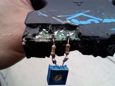
I had an old Pro-Tec modified 61X CDI that broke. I took it apart to pull out the pot and resistors. They use 36k, 1% tollerance resistors. (Orange, Blue, Orange, Brown)

You can see what they are by looking at the resistor color code chart here: http://www.electronixexpress.com/tips/clr_code.gif

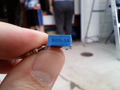
..and you can clearly see where they solder this on the PCB. The pot has 500k 53 written clearly on the side. I measured it and it was 0.5 MegaOhms which is 500k Ohms.

I'm going to buy a replacement CDI and install this on it now that I have it removed.
 

Attachments

  • ProTecMod.jpg
    ProTecMod.jpg
    51.6 KB · Views: 1,068
  • 500k.jpg
    500k.jpg
    35.2 KB · Views: 854
Last edited:

Lucifer

Jet Junkie
Location
Croydon PA
My other addiction is modding synthesizers. Mostly analog/digital hybrids from the early 80's.
ANY electronic circuit can be modified whether its analog or digital or both. It just takes time and persistance in reverse engineering a circuit or decompiling an instruction set.

I'm getting really curious now.....
 
Here are the pics I have that show where to connect a jumper to disable the rev limiter.

In the first pic with the blue line connecting the two soder points, it shows a different sodering point than in the pic with the yellow arrows pointing them out. The two points are right next to eachother, im not sure which one to connect the jump to.

Ive got my cdi cut open already, does anyone know exactly which point to use?


cdi%20mod.jpg


or

cdi%20mod%202.jpg
 

cattledog

EH TEAM RACING
Location
toronto canada
I had an old Pro-Tec modified 61X CDI that broke. I took it apart to pull out the pot and resistors. They use 36k, 1% tollerance resistors. (Orange, Blue, Orange, Brown)

You can see what they are by looking at the resistor color code chart here: http://www.electronixexpress.com/tips/clr_code.gif

..and you can clearly see where they solder this on the PCB. The pot has 500k 53 written clearly on the side. I measured it and it was 0.5 MegaOhms which is 500k Ohms.

I'm going to buy a replacement CDI and install this on it now that I have it removed.

bringing back a old thread i have a pro tec cdi for a 62t the adjusting dial is broken just keeps spining can i just solder the two wires togeher, that go two adjuster knob and have the highest rpm
 

Layne

Addicted.
Location
Springfield, MO
bringing back a old thread i have a pro tec cdi for a 62t the adjusting dial is broken just keeps spining can i just solder the two wires togeher, that go two adjuster knob and have the highest rpm

After reading this thread about 3 times now. You MUST have a resistance, below 50-60 ohms your CDI will not function.

It would be a much better idea to just remove the wires altogether rather than solder them together. Ideally I think you should do the 36k resistors and the 500k pot.

Just ordered myself some. 10x 36k + 3x 500ohm = $7 shipped. Super cheap.
 
Last edited:
Blue or yellow jumper? - Still confused, please help!!

I hope that I am not just being dense but I too can't tell whether I should be using the blue or yellow jumper from Superjett's pics. and I can't find a definitive answer.
Hull strengthened, porting completed, tote rebuilt, CDI box cut open, soldering iron warmed up, desperate to get on the water!
Can anyone help?
 
Top Bottom