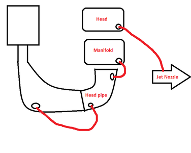
B-pipe cooling, routing water lines

MikeyB

H2O-Addict®
Location
Michigan
Why do you guys run the water from the head to the bottom of the elbow on the pipe? See pic below. My FP directions show the hose from the head going to the top fitting on the pipe not the bottom. Is this better for some reason? The pic below is basically my set up except Im running to the top fitting like FP advised.Thanks


Ive been wondering this too, did I miss something here?

"Install the 3/8" x 13" waterline (item #10) from the cylinder head fitting to the top barbed fitting on the headpipe and secure both with a #6 clamp."

http://www.factorypipe.com/media/instructions/yamaha/701SJ01.pdf (Page 3, Paragraph 5)
 
Last edited:
I run the rear outlet to the bottom of the head pipe because to me it seems like it would "fill" the head pipe better... But I've ran it both ways and it seems like I can close all the screws a little more and the pipe seems cooler.
 
i drilled my hull for dual cooling over the winter im not running a superjet but a heavily modded 550 with a pjs viper 7000 engine.. i incorporated a flush valve just after the lines enter the engine bay because my ski does see salt water on occasion.. i used a tee on one line for the exhaust mani so it has 2 inlets and a tee fitting when the exit the head to even everything out.. the pipe also has a dedicated line for better fine tuning of the pipe.. the theory behind this and this is according to factory pipe too because it builds more pressure in the head pipe allowing the injection to "mist" having a better affect on cooling the pipe at lower rpms yet allowing it to heat up more for more top end power.. the cooler water also creates more effect and you can run the pipe a little dryer as well.. my pipe doesnt have a bottom water fitting so i just go in from the front.. water bypass with a adjustable water valve as the pipe restrictor and the flow control valve.. the ski definitely seems to have better throttle response and more snap when it comes on the pipe. before, i had single cooling setup standard with water exiting the head into the headpipe.. here is a pic..
 

Attachments

  • IMG_20120527_221037.jpg
    IMG_20120527_221037.jpg
    59.9 KB · Views: 524
in dealing with over cooling issues here is the answer i got from jetworks..as mentioned before..so many different ways of doing things ;-)

"If the water is cold year round then all you need is one line to cool the engine and you can control temps by changing out the pills in our restrictor kits.

The second cooling line you can go straight to the headpipe lower fitting and the top of the headpipe have it go to the stinger and have a tee between the stinger and have a full 3/8 bypass. I would also add a restricter to the stinger area to limit to 2 mm and put a flow valve there. The flow valve after the tee, and the restrictor just before the stinger.
I dont see the need to use the second line to the engine unless you are holding it wide open at higher speeds.
The reason we like the dedicated cooling line to the engine is you can alter the water flow without affecting the exhaust water pressure and flow characteristics."

that last line to me seems to make the most sense specially for guys who go from cold, to warm, to hot back to cold water..this way it seems you can regularly adjust your engine temps without having to always chase your tail tuning the pipe as well..
 
Last edited:
i love the clear conscise explanation and answers to the questions i had sent..by comparison i sent the same email to wamilton and received this confusing reply which doesnt address the question at all...guess who's getting my business.

here for your viewing pleasure is the exchange.. ill skip the first email detailing my problem and set up, the reply was to adjust my set screws in my b-pipe..here goes

ME - [FONT=&quot]your diagram and instruction to run as such are almost exactly how i have it in my ski currently, which i had listed in my original email.the only change is you go from top of head pipe to stinger with a 3/8 bypass and front cylinder head goes direct overboard.
mine is top of head to pisser, front cylinder head to bypass/stinger/overboard
as well as the settings on the b-pipe set screws, mine are identical.

this slight change in line routing in no way helps resolve the high flow of cold water through the engine nor does it address th need to raise operating engine temp.

what i need to do is keep the water in the cylinders longer to warm the engine temp as the water coming out both pissers is cold.
hence my question about restricting the flow coming out of the head.

hope this clarifies things a bit.

TO WHICH I GOT THIS REPLY -
[/FONT][FONT=&quot]You thinking too hard, in reality you will not benefit from the change you want to do, your water temperature will go up in the near future, plus your ski gets hot on the manifold plate that is inefficient due to the restrictions due to the original design from the factory. [/FONT]

UHMM..OK.. so not even remotely close to the topic..not to mention the water temp will go up eventually comment..ya..sure it will..here in central western canada that should be..oh...when the polar ice cap melts..

i feel almost as if this was some bot replying without ever addressing the legitimate question..such a huge contrast from the professionalism over at jetworks.
 
Here is the X-Scream diagram (rear exit).. I was told by them to never put more than 3 items on a cooling circuit. So, one line would cool the exhaust manifold, cylinder and head pipe and the other cooling line would cool the exhaust manifold, cylinder and stinger... This balances the cooling lines and keeps the water temps down. Not sure if this is better or not but, that's what I was told by the boys at X-Scream. Followed it on 5 skis now without any issues...ImageUploadedByTapatalk1372215240.045274.jpg
 
Last edited:
I have a 701 stock head with a b-pipe the cooling line on the manifold for the b pipe looks like it should go to the inlet on the port side of the coupler. in the photos i don't know if that line is a stock rear drainage or a secondary inlet. If it is an inlet the drawing is how I'm thinking of running the lines. but with the stock head there is only one decent size exit route, is it best to tie that into the pipe? or out both the big and little head outlet to pissers and run the secondary inlet? to the bottom of the pipe? I bought the modded hull when it had a stock engine and but don't know what he had in there before i bought it. i have intentions of getting a aftermarket head at some point but budget only allows for piecemeal additions. advice would be greatly appreciated
 

Attachments

  • cooling.png
    cooling.png
    238.7 KB · Views: 361
  • 20140407_214938.jpg
    20140407_214938.jpg
    127.8 KB · Views: 320

swapmeet

Brotastic
Location
Arlington TX
The second line depends on your pump. If you pump has two cooling outlet lines coming from the stator section (vanes), then the one with the green hose is for cooling.

If there is only one coming from the stator section.... Well you know.

As far as you drawing goes... Explain the dual outlet ports on the head vs you saying only one?
 
Jetpilot08s picture on this thread of his, 12 post before this one #zero's post, the heads have 2 full size hose barbs. My stock head has one full size (at a 90degree) and a small vertical barb. if I Tap the pump to run dual cooling do I need to tap the head too? on a side note tapping the pump to run dual cooling do I drill it directly across from the other pick up?
 
Location
oklahoma
ok so i am new to the site and to waveblasters so please bare with me. Like i said i just bought a 94 blaster, the guy i bought it from told me it was set up for dual cooling.
i am wanting to try and run the cooling off the jet pump and only use the oem bilge on the other side of the nozzle. The problem is that all the pluming circuits i can find are different from what is on my engine. my head and manifold only have one fitting each. The ski has a factory b pipe exhaust. I have attached two rough drawings of the only two ways i could see the system being hooked up.
option1.png option2.png
 

JMew03

The call me Mew Mew
Location
DFW,TX
If it is a stock engine with a b-pipe I wouldn't waste time doing dual cooling. Seems like overkill to me.

With that being said..
The pump should feed the exhaust manifold. The head and the backside of the head pipe should be connected. The front of the head pipe should go to the stinger (how you have it). Put a pisser between the head pipe and stinger so you know everything is flowing.
 
Location
oklahoma
The Head that is on my engine is a Yamaha performance head that was made by west coast.

If I have a 4mm pisser do I need to flow control before the pisser or with the pisser control it enough?

option3.png
 
Location
iowa
Just read all this but did not find a piping arrangement like this: It's working good for me. Each cylinder gets a pisser located in front above bond line. Head pipe water dumps out old oil sight glass area. The ball valve helps warm up pipe and creates good pressure for water injection. 74-78 degree lake water. Top closed, middle closed, bottom 1/2 open. I've never had exhaust chamber get hot, certainly not near coupler. Head and cylinder stay warm. Head pipe water temp 135-140 deg guessing and head water pissers 110-115 deg again guessing with my hand. No resrictors (yet)image.jpg
 

JMew03

The call me Mew Mew
Location
DFW,TX
Where does all the water behind the flow control go? Seems like using a flow control without a pisser would be like kinking a water house.
 
Location
iowa
I use Y fittings before manifold, not T's. You don't need a pisser or bypass near FCV. IMO. Unused water during a closed FCV would simply travel through engine. I'm using a mag pump with big hub hooker prop, plenty of water supply and pressure.
 
Ok I want to make sure my setup is ok by everybody, I am running dual cooling to 2 fittings in the manifold, then I have a blowsion head with 2 water outlets, 1 water outlet goes to the top of the head pipe and the other goes straight to a pisser, then I have a line that goes from the bottom of the head pipe to the stinger with a tee to a pisser and a flow control valve before the stinger, sound good?

1c7287e9c4a841b28d4c493cb7b83b0e.jpg
 
This is a great thred so i dont care if im resurecting an old thred maybe someone else will like to read it.

My question is can some one please tell me how the water flows through the system so i can picture it properly. Example pump to exhaust mani to .......

Sent from my SAMSUNG-SM-G930A using Tapatalk
 
Top Bottom