Budget total loss?

Mouthfulloflake

ISJWTA member #2
Location
NW Arkansas
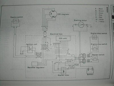
according to this pic it seems the yamaha superjet CDI gets a 12VDC rectified feed ( I assume for its operation) and then the unrectified AC voltage from the cdi charge windings also ( I assume for charging the coil)

I don't see anywhere it would get 20-60 Volts DC ( unless the regulator/rectifier was faulty)


Depends on the particular setup of the CDI. I think.
 

Attachments

  • SJ electrical diagram.jpg
    SJ electrical diagram.jpg
    61.7 KB · Views: 37

Matt_E

steals hub caps from cars
Site Supporter
Location
at peace
"Charging the coil" is a multi-step process.

If I remember correctly, it gets doubled once, then put through a diode network (to get rectified), then into a transformer.
The secondary of that tx feeds the coil.

It is a bit more complex than that, but that's the basics.

EDIT: 12VDC is for charging the battery, nothing else.

 

Waternut

Customizing addict
Location
Macon, GA
^^^
I knew there was a reason I went into structures instead of electronics. I understand those schematics but it takes forever to fully figure out what's going on. lol
 

Mouthfulloflake

ISJWTA member #2
Location
NW Arkansas
in that diagram, the CDI unit, is connected to the rectified output of the regulator/recitifiar.

and the other two coils are connected to the CDI unit too.

do you think it takes in that AC from the charge coil and then rectifies it into DC to bump the ignition coil?

I really doubt it, most modern CDI unit charge the coil with AC voltage.

either way...

my initial point was, there isnt 20-60 Volts DC coming anywhere from a superjet stator.
My guess is in the manual he read the OPEN CIRCUIT voltage of the battery charging circuit ( DC side of the rectifier), instead of the cdi charging circuit.

the battery holds the voltage down to 15 volts or whatever.. open circuit MIght be as much as 60 volts DC

I only point that out for folks that are trouble shooting in the future, its hard enough to find info on these things.


"Charging the coil" is a multi-step process.

If I remember correctly, it gets doubled once, then put through a diode network (to get rectified), then into a transformer.
The secondary of that tx feeds the coil.

It is a bit more complex than that, but that's the basics.

EDIT: 12VDC is for charging the battery, nothing else.
 
Last edited:

keefer

T1
Location
Tennessee
Yeah... I always thought the magnets would crate an AC voltage to the CDI? :scratchchin:

You are right, a magneto will produce an AC voltage with a sinusoidal waveform of varying frequencies depending on RPM. I would guess that the CDI has internal rectifier that converts it to DC and regulates it for use in powering the rest of the CDI circuitry.
If I ever get around to completely digging all of the potting compound from an old CDI, I would know more about what is going on in there. It would be a PIA to dig all that crap out while avoiding the little white chips and not destroying the components while preserving the markings on the to determine their values. Just buy a MSD TL and be done with it.
 

Matt_E

steals hub caps from cars
Site Supporter
Location
at peace
in that diagram, the CDI unit, is connected to the rectified output of the regulator/recitifiar.

and the other two coils are connected to the CDI unit too.

do you think it takes in that AC from the charge coil and then rectifies it into DC to bump the ignition coil?

I really doubt it, most modern CDI unit charge the coil with AC voltage.

either way...

my initial point was, there isnt 20-60 Volts DC coming anywhere from a superjet stator.
My guess is in the manual he read the OPEN CIRCUIT voltage of the battery charging circuit ( DC side of the rectifier), instead of the cdi charging circuit.

the battery holds the voltage down to 15 volts or whatever.. open circuit MIght be as much as 60 volts DC

I only point that out for folks that are trouble shooting in the future, its hard enough to find info on these things.

I didn't say it's using DC to charge the coil.
It's RECTIFIED....that is not equivalent to turning AC into DC.
It keeps both peaks in the positive, which just means you get POSITIVE pulse on the coil, and not an alternating signal.

Besides, it doesn't directly charge the coil anyways.

The incoming AC signal is doubled, rectified, charges a capacitor. The pulse coil triggers a discharge of the cap, across the primary of a Transformer (or another voltage multiplier circuit).
And that is what goes into the coil
 
Last edited:

Kaveman

Born in USA(not Kenya)
Yeah... I always thought the magnets would crate an AC voltage to the CDI? :scratchchin:
My bad, you are correct. I have the Snap On peak voltage adapter. When using it you get no reading in the ACV setting and must set to DCV to get a reading. The readings are accurate with supplied specs. Has something to do with how it holds the spikes and slows down the drop. The Ignitionmate I have reads in ACV, just bigger and bulkier to haul around.
 

keefer

T1
Location
Tennessee
in that diagram, the CDI unit, is connected to the rectified output of the regulator/recitifiar.

and the other two coils are connected to the CDI unit too.

do you think it takes in that AC from the charge coil and then rectifies it into DC to bump the ignition coil?

I really doubt it, most modern CDI unit charge the coil with AC voltage.

either way...

my initial point was, there isnt 20-60 Volts DC coming anywhere from a superjet stator.
My guess is in the manual he read the OPEN CIRCUIT voltage of the battery charging circuit ( DC side of the rectifier), instead of the cdi charging circuit.

the battery holds the voltage down to 15 volts or whatever.. open circuit MIght be as much as 60 volts DC

I only point that out for folks that are trouble shooting in the future, its hard enough to find info on these things.

Matt is right, re read the diagram. The only thing that gets rectified & regulated is the AC from the green wires from the lighting coil. The red wire output of the rectifier only goes through the fuse to the start switch and back to the solenoid. The 12vdc source is only to start the engine & then the return current charges the battery, thats it. The cdi is only energized by the AC from the charge coil. What it does internally to further rectify, double, oscillate, retard, and rev limit would have to be determined by circuit analysis when a CDI circuit board schematic could be obtained.
 

WFO Speedracer

A lifetime ban is like a lifetime warranty !
Location
Alabama
Ok I have to step in here,when you say its rectified that means exactly that its converted from AC to DC.The AC voltage is sent through a series of diodes wired in a such a way so as to only let current flow in one direction thats what diodes do(READ RECTIFIER) ,half of the AC wave is sent to ground,whats left is DC voltage which goes out the output wire on the regulator back to the battery .
 
Last edited:

Mouthfulloflake

ISJWTA member #2
Location
NW Arkansas
Matt_E, and Keefer.

I know how a CDI ignition works.

My point, ONCE again...

there is no way he was gettnig 20-60 volts DC from ANY stator output on a superjet.

I guess cant explain things well enough for folks to follow along, ill stop trying to clarify things if that is the case, it simply isnt worth trying to explain them over, and over again.
 

keefer

T1
Location
Tennessee
I was just trying to clarify that the rectified output from the regulator on the red wire never goes to the CDI as you stated. Not a big deal. Do you have a schematic of the Yamaha CDI? I would like to know more on how or if it actually advances the spark and how does it provide retard if any. Has anyone ever mapped the actual timing of a Yamaha analog CDI? Just curious, not trying to question your knowledge.
 

Mouthfulloflake

ISJWTA member #2
Location
NW Arkansas
right.

I mis read the KILL white wire, its not from the 12v side of the rectifiar.

regardless, I see where Kaveman explained his DC findings above.

No big deal, it was an attempt from me to keep the information GOOD for future searchers.

BUT, since I cant verbalize things well, the post got muddied, and its basically JUNK now to anyone that doesnt already have a pretty good understanding of how these work.


I was just trying to clarify that the rectified output from the regulator on the red wire never goes to the CDI as you stated. Not a big deal. Do you have a schematic of the Yamaha CDI? I would like to know more on how or if it actually advances the spark and how does it provide retard if any. Has anyone ever mapped the actual timing of a Yamaha analog CDI? Just curious, not trying to question your knowledge.
 

WFO Speedracer

A lifetime ban is like a lifetime warranty !
Location
Alabama
It reads the AC voltage sent to it and retards the timing when a certain voltage is reached more voltage =more rpm.
 

keefer

T1
Location
Tennessee
Ok I have to step in here,when you say its rectified that means exactly that its converted from AC to DC.The AC voltage is sent through a series of diodes wired in a such a way so as to only let current flow in one direction thats what diodes do(READ RECTIFIER) ,half of the AC wave is sent to ground,whats left is DC voltage which goes out the output wire on the regulator back to the battery .

Yep the module prolly has a full wave bridge type rectifier series of diodes and a DC regulator IC. Might be all on one chip for all we know. I doubt Mitsubishi will tell us...

As far as the retard scheme goes, that makes a lot of sense. That is a pretty simple way of getting it done. Those CDI units can't be too complex, there are not that many components on the board and it looks to be all analog discrete components. Not even a Linear IC onboard from what I can tell. I really need to dig all the potting compound away from a CDI and draw it all out. Just a lot of work for not much return IMO, maybe curiosity will get the best of me one day and I will do it if I ever get that bored.
 
Last edited:

SUPERTUNE

Race Gas Rules
Location
Clearwater Fl.
The stock Superjet CDI's (6m6, 61x and 62t) all start and run at lower timing then add timing as the engine speed increases. If you look at a Yamaha OEM service manual, it states to set ignition timing to 21 degrees @ 6000 RPM's.
This method is used as to not run too much timing for wide open throttle.
If you map it on a timing light you might get about 18 degrees at idle and will see it slowly advance up to the max of 21* as the rpm's go up and all of the max timing is all in at about 5000 rpm's. Yamaha did this on purpose to match the low compression, be very tame (not violent) and still have some power at top speed by advancing the ignition timing.
 

keefer

T1
Location
Tennessee
Thanks Chuck, I figured if anyone would know this it would be you. I always thought they retarded after a certain RPM instead of starting retarded and building up to a final advance point. What is the static timing at the stator?
 
Forgive me if I'm wrong.:newbie: The stock CDI has less timing at lower rpms and then advances timing in higher rpms? This is not optimal for a freestyle motor because you would want more timing at low rpms, then in the higher rpms you would want less timing to protect the engine? (especially if you’re running high compression) Correct?

So a TL ignition system pretty much does the opposite for the stock cdi? (As far as timing goes) as to give more timing in lower rpms and less in higher rpms? I hear they are programmable. This means you can actually change its timing characteristics? Is there software that comes with it? Also do most actually utilize this feature or just run the pre set specs?

How diffrent is the TL timing from an msd enhancer?

thanks
 

Matt_E

steals hub caps from cars
Site Supporter
Location
at peace
Forgive me if I'm wrong.:newbie: The stock CDI has less timing at lower rpms and then advances timing in higher rpms? This is not optimal for a freestyle motor because you would want more timing at low rpms, then in the higher rpms you would want less timing to protect the engine? (especially if you’re running high compression) Correct?

So a TL ignition system pretty much does the opposite for the stock cdi? (As far as timing goes) as to give more timing in lower rpms and less in higher rpms? I hear they are programmable. This means you can actually change its timing characteristics? Is there software that comes with it? Also do most actually utilize this feature or just run the pre set specs?

How diffrent is the TL timing from an msd enhancer?

thanks

You got it backwards. It starts out at more advance, and retards further in the RPM range.
Mouthfull....I agree on all counts.
 
Top Bottom