Super Jet 1996 Round Nose SuperJet Project

Roseand

The Weaponizer
Site Supporter
Location
Wisconsin
You've got the whole entire winter to work on stuff now though. I believe with that mat, it's not really that strong anyways.. You might be able to cut it at the bondline, then with a chisel or whatever, get between the hull and the fiberglass below the bondline, and rip/pray it off. I'd recommend grinding the ribs, because that just leaves room for air bubbles, and you don't want that. Then do your prep work, fill the bondline with thickened epoxy resin, and lay one layer covering top to bottom of biaxial fiberglass. If I were to overlap anything, I'd have a 6 inch strip over the bondline, a 12 inch strip over that, and then one top to bottom that goes all the way across. The side by side overlapping is different, maybe it works good, I just haven't seen it done that way. As long as you prepped the surface on the top deck well, that polyester resin should still stick and you can put another laminate on top of that. Check out the tech faq, there's all kinds of info on reinforcing and what supplies to use. That's where I've learned everything. You've got a crazy long off season, might as well do things right and not have to go back and do it again :)
Just my .02
 
Last edited:
It's good .02 though =) Granted we do have a brutal amount of downtime, most of that time is so far into the frozen status that I would normally wait until late April or so to do any new work. One other thing that I get a little chuckle out of is that I just recently adopted a repair job for a couple of buddies...7 skis! lol. Ah well, I don't mind allowing my ski to run for a year before I decide to dig into more work. Who knows though, I might jump into it again this spring. I do know that the overlapping info is good though, a buddy of mine used to build ultralight aircraft and he used that method in a lot of various conditions. I can't remember specifically where he used it but I know it works.
 

Roseand

The Weaponizer
Site Supporter
Location
Wisconsin
Edited what I said about the overlapping in the above post. Now it'll make more sense to what I was saying.
 
Porting

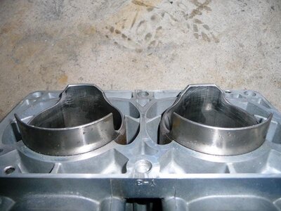
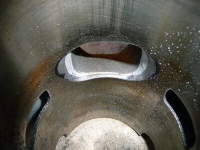
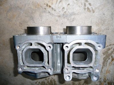
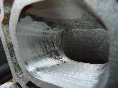
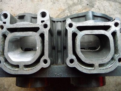
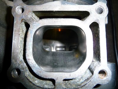
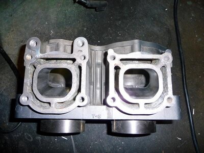
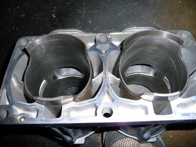
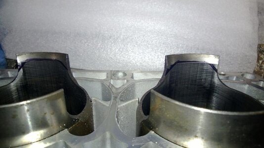
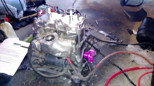
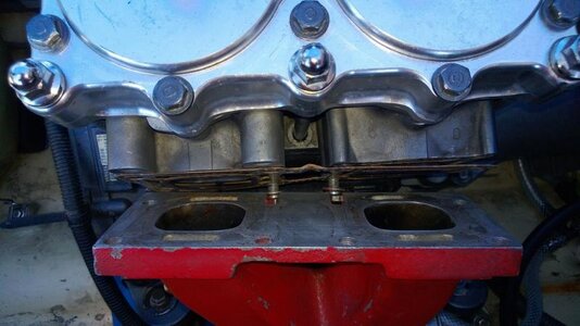
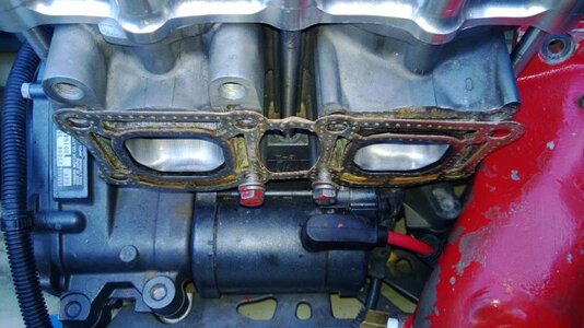
With all the hull work and driveline modifications in place, it was time to get inside the engine and work with the ports. The first and easiest thing to do was remove a healthy portion of the intake side of the cylinder skirt. All it took was a good grinding with a softpad and re-establish the angles and lead-in for the pistons to install smoothly. I used the RaceLogic port templates and marked the skirts accordingly with black marker and took to the grinder. Next was opening up the exhaust ports and giving them a nice, almost mirror finish. I have read in the past people that question polishing the exhaust ports and I have found two reasonable reasons why. In the first photo of the polishing on the manifold side, you will notice that with just a mild single pass with the sanding drum on the Dremel there are several imperfections in the casting. The bumps and pockets will create turbulent airflow and create mini-vortexes disrupting a clean dedicated airflow. Polishing the ports like this is especially important at this location as well because these pockets and bumps have the potential to collect any carbon soot and build up, before you know it you have a carbon blockage if your oil quality is not there or are just mixing a little too much. One nice thing about the polished finish is that any unburnt oil residue will just wipe off clean in addition to the improved airflow. While in the polishing stages, I made it a point of opening up the radius of the corners a small amount but only enough to match the gasket more efficiently. Originally these corners were somewhat small, so it was good to increase them. Now they also match the cylinder porting radius in good proportion. The Yamaha exhaust channels are fairly direct with minimal variation in the flow angles, but there is always room for improvement. The finished product speaks for itself.

When porting cylinder port windows one can't rush it, I didn't want them to look like a machine shop apprentice went at them with a dull file. It is necessary to take slow and controlled swooping motions while remembering that you don't want any part of the window to be too widely open or too sharply cornered. Those piston rings need to be eased across the the window, not given a long narrow corner to hook into and break or a big wide one allowing them to bow out into and snag. One thing to keep mind as well, for obtaining power increases across the powerband the cylinder windows should not be raised or lowered, just widened. The typical rule of thumb is not to exceed about 70% of the bore, for example if you had a 100mm diameter bore, your port window should not be wider than 70mm. I have read that 75% is the maximum but this is one occassion where less is more. I personally shoot a little under that number and stay around 67%, the power increase is substantially noticeable and the piece of mind knowing that the limit has not been maxed or unknowingly past, is an insurance unto its own.
 

Attachments

  • Intake Side Mod 2.jpg
    Intake Side Mod 2.jpg
    70.1 KB · Views: 152
  • Porting 2.jpg
    Porting 2.jpg
    68.5 KB · Views: 158
  • Porting 3.jpg
    Porting 3.jpg
    83 KB · Views: 151
  • Porting 4.jpg
    Porting 4.jpg
    54.8 KB · Views: 151
  • Porting 5.jpg
    Porting 5.jpg
    81.5 KB · Views: 151
  • Porting 6.jpg
    Porting 6.jpg
    76 KB · Views: 148
  • Porting 7.jpg
    Porting 7.jpg
    77.8 KB · Views: 143
  • Porting 8.jpg
    Porting 8.jpg
    74.3 KB · Views: 148
  • Intake Side Mod 1.jpg
    Intake Side Mod 1.jpg
    44.3 KB · Views: 152
Last edited:
Reed Stuffers

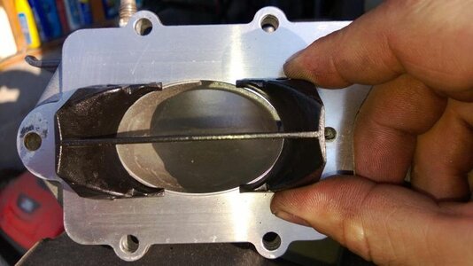
There isn't much info floating around on reed stuffers and with understandable reason. They are not a widely used item and the opinions of gains are as equally in favor of, as they are against. This past summer I installed a set of R&D plastic reed stuffers. They do fit in very nicely and do help the throttle get a very slightly bit more crisp, but they do come with a cost. Their intention is to blueprint the intake tract making a venturi effect at the reed cages where the air volume will be somewhat large and slow moving. What I have found is that although this is certainly something to consider, on the flip side the reeds on the outer portion of the cages will not see the dispersion of the fuel charge in the same manner as they would without the stuffers. With the venturi effect taking place, the fuel charge is also directed more toward the center reed petals instead of shotgunning outward filling the entire cage. When the fuel charge gets concentrated to one location like that, a few things can or do occur. Some of the fuel charge will collect and go back to a droplet state instead of atomizing which would create a rich running condition regardless of carburetor settings, the fuel charge will not fill the available airspace volume the entire cage offers reducing full atomization and crank lubrication, or trenches will collect the fuel droplets eventually creating a blue foam fuel/oil build up in the trenches reducing airflow and fuel charge volume. As far as crank bearings and lubrication goes with stuffers, it is probably not something to be worried about but when I pulled my stuffers I did notice that my cages were always wet just enough to almost drip. Another observation was that the center two reeds were with a full wet film but the outer reeds were not so much which is why I mention that the concentration appears to be hanging up on the center reeds more so than not.

As far as construction is concerned, once again I have learned that even the mod parts sometimes need to be modded. In the photos below you will notice how much overhang the corners of the stuffers had. I noticed this on the first time I removed the intake while I was testing between a single and dual intake set-up...also did not notice any difference in performance but I did notice a difference in fuel consumption. Strangely enough the single SBN44 still drank a little more than the dual 38's. But back to the stuffers, to prevent the fuel from slamming into the corners of the stuffers and creating drips, I grabbed the trusty Dremel and a metal burr tool to change the corners into points. There wasn't any noticeable improvements in performance but at least the airflow impedance was removed. Another issue I have read about over the last year or so is that the plastic stuffers will only last for so long before they start to warp and twist. The crossmember in the center of the stuffers will eventually turn into a spoiler and change the direction of at least half the airflow, that would inevitably hurt proper carburetion. This is certainly not to say that they don't work, but for what little is gained vs. what all has to be done for proper fitment and limited durability, this will be the last set of stuffers I use. The aluminum stuffers from what I have read don't quite have the fit precision that the plastic R&D's do, but that is to be expected, not all cages are going to be identical to each other so having a 100% fitting aluminum stuffer is simply not possible.
 

Attachments

  • Reed Stuffer Mod 1.jpg
    Reed Stuffer Mod 1.jpg
    45.8 KB · Views: 144
  • Reed Stuffer Mod 2.jpg
    Reed Stuffer Mod 2.jpg
    51 KB · Views: 149
Kenny Keepers (Engine Keepers)

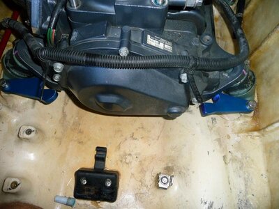
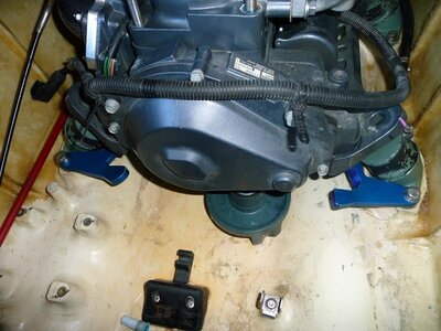
This is another little area that seems to have very limited info on. Although these guys are not a difficult thing to install, when you buy them used trying to find pics showing which way they get installed seems to be somewhat limited. So I thought I would just toss up a couple of photos of how they look installed. Nothing special, but certainly remember that the bolts in the motor mounts to the hull need to be replaced with longer ones by about 1/4" longer.
 

Attachments

  • Kenny Keepers 2.jpg
    Kenny Keepers 2.jpg
    70.1 KB · Views: 151
  • Kenny Keepers 1.jpg
    Kenny Keepers 1.jpg
    74.6 KB · Views: 158
Thanks man, I have done porting before and most of these mods. But there is just something really exciting about doing it to a ski with real freestyle potential. In just one and a half seasons this ski has brought my game up to new levels. The Speedwerx pipe you and Octane helped me with will be coming up soon ;)

Edit/Addition: For those of y'all that have been following this build, Wanderer has been a huge help and a solid stand-up guy. Many many thanks for everything my friend...or as the youngens say, "mad props dooood" =D
 
Last edited:
Exhaust Pipes - Dry Pipes and Cheater Pipes

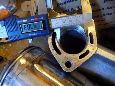
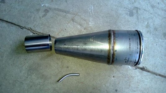
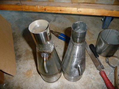
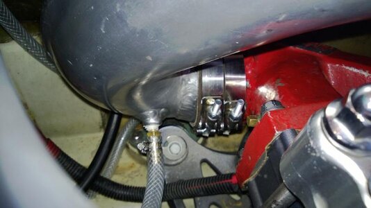
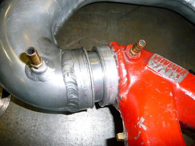
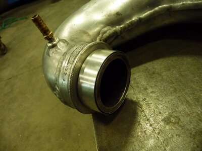
When the porting work was all completed, the manifold and pipe selection was next. My first thought was affordability. I sank virtually all of my available finances into the parts mentioned from the start of this Spring past up to the middle of the summer. I knew that all the engine work done, the ports, the polishing, the intake, an ADA girdled head kit...all of it would be for the most part unnoticed without a pipe to compliment it. Since the stock pipe was just that, stock and referred to by Matt_E as a "breadbox"...pfffHAHAHA...I still laugh about that awesome observation, thank you Matt =D I decided at the time that my only affordable option was one that worked extremely well on my other ski...a poor man's B-pipe. I did some hefty modifications to a Kawi 650sx pipe, mounted on a Coffman's manifold bored out to about 48mm. So I matched the head pipe and gasket to compliment the manifold dimensions. I then did all the necessary mod work needed to the headpipe and expansion chamber. In the head pipe, I had the 1/4" water injection hole welded and re-drilled to 1/8", drilled and tapped the top of the headpipe for a 1/8" NPT fitting, drilled a 1/8" hole in the stinger and had a water inlet welded on over top. Then I added an extra 4 1/2" of length to the expansion chamber for that full on bottom end punch. This can be coupled together with 4" plumbing couplers found at Home Depot and they stand up very well to the heat and vibration. The only key is to use 4 gear clamps, not the two that comes with the coupler. As for the little water drain fitting on the bottom of the 650sx pipe, I just tapped it I believe to be #6 or #8 pitch, added silicone to a screw and locked it down, this can also be welded if you choose to go that route. What I also didn't like and chose to change was the diameter of the stinger outlet size. The Yamaha exhaust hose is about 2" I.D. and the Kawi stinger is about 1 3/4". So I cut it off and had a 2" I.D. piece welded on. I know this is nothing like a genuine Factory Pipe B-pipe, but I must say, when there are no other options between this method or stock, this well out-performs the stock set-up by far. I have learned over the last few months too after working on a few Blasters, that the installation of the true B-pipe is certainly one I would like to avoid in the future. I found it very difficult to work on and install. It might be better with the SuperJet, but for the price at the time and knowing what I know now, it's not for me.

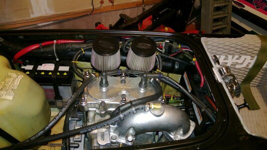
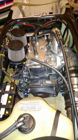
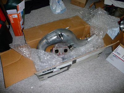
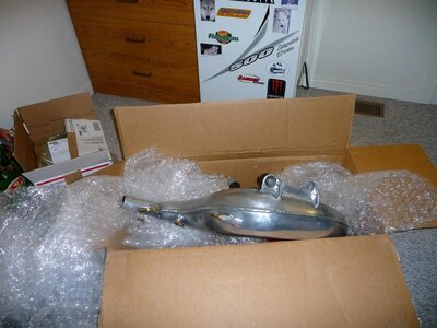
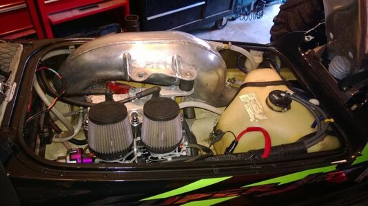
So in the first few photos, you will see the modified 650sx pipe (cheater pipe) installed. As mentioned, it worked very well but after a couple of months I decided that I needed to move up and get a real, meant for the SuperJet, pipe. So I bought a Speedwerx race version pipe. At the time I first installed it, I really was disappointed in it. I found that the only benefit was it had unreal top end, but the bottom end was less than what I had with the cheater pipe. Being very new to a full on dry pipe, I was unaware of how to route the cooling lines and set this beast up. With many hours of frustration, installation and removal I was fixing to sell it. Between Wanderer, Octane and the others that helped me go through the set-up with a fine toothed comb we dialed in the monster and I have absolutely no desire to let this one go now. The issues I was facing were cooling entering the airstream when it should not have been at all, cooling lines that it needed and I did not have, and a dual cooling pump set-up that I did not have. To make this pipe really work, you need to have dual cooling. One line supplies the exhaust manifold, one supplies the pipe waterjacket. To make this pipe really work well, you also need to re-jet your carb. I went with a 145 main, and 80 pilot. Something to keep in mind is that Mikuni carbs can only process so much fuel at a time and the total jetting capacity for the SBN's is about 220 total jetting equivalent. What this means is, you add your pilot size (80) and main (145) together to come out with a total jetting of 225. My needles and seats are stock 1.5 with stock weight springs. To compliment the new carb settings, you also need to help improve the breathing. For this I removed the choke butterflies, added in primer fittings and removed the stock airbox for R&D Pro-Lock flame arrestors.
 

Attachments

  • Finihed Engine.jpg
    Finihed Engine.jpg
    70.3 KB · Views: 144
  • Headpipe Bore.jpg
    Headpipe Bore.jpg
    77.2 KB · Views: 143
  • Stinger Mod.jpg
    Stinger Mod.jpg
    58.8 KB · Views: 147
  • Stinger Mod 1.jpg
    Stinger Mod 1.jpg
    71.5 KB · Views: 145
  • Engine B-Pipe 1.jpg
    Engine B-Pipe 1.jpg
    63.3 KB · Views: 148
  • Engine B-Pipe 2.jpg
    Engine B-Pipe 2.jpg
    71.6 KB · Views: 150
Last edited:
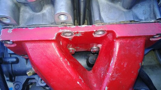
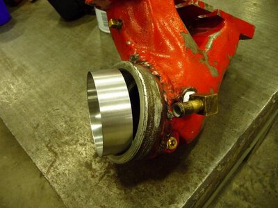
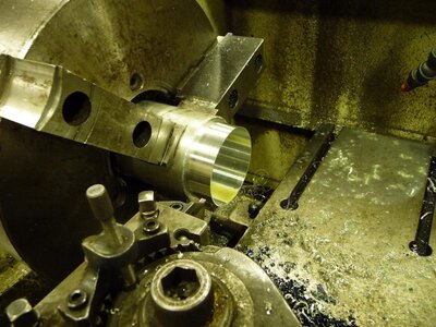
With the carbs rebuilt, freshly jetted and installed kits, and improved airflow flame arrestors, it was time to install the pipe again. One thing to remember with the Riva manifolds is that they are not easy to install. The easiest method I have found is to hang the gasket on the two lower bolts and screw them into the block a few threads only. This way you can slide the manifold onto the bolts and also have the bolts as a holding fixture so you can get the other bolts installed. One thing I found when I installed the pipe into the manifold was how sloppy of a fit it was and the O-rings made the installation a bit of a tough job when they would rub the inside of the manifold walls. So I decided to set up the lathe at work and make a thin little spacer ring. It is a 0.030" thick ring that slips tightly over the O-rings and very nicely inside the the manifold. It also made installation much smoother, brought the pipe up tight to the manifold and kept it well aligned for the heavy duty boat exhaust hose coupler I bought. With the use of this sleeve ring, coupler, and T-bolt clamps, this pipe has been a solid set-up. When the pipe arrived the only thing it was missing was a mounting plate for the lord mounts, so that was another part I had to make at work but it was easy enough to do.
 

Attachments

  • Speedwerx Manifold Hanging 3.jpg
    Speedwerx Manifold Hanging 3.jpg
    55.6 KB · Views: 152
  • Speedwerx Manifold Hanging 4.jpg
    Speedwerx Manifold Hanging 4.jpg
    43 KB · Views: 152
  • Speedwerx Manifold Hanging 2.jpg
    Speedwerx Manifold Hanging 2.jpg
    50.7 KB · Views: 149
  • Speedwerx Manifold Hanging 1.jpg
    Speedwerx Manifold Hanging 1.jpg
    62.9 KB · Views: 149
  • Speedwerx Pipe Ring 4.jpg
    Speedwerx Pipe Ring 4.jpg
    66.7 KB · Views: 153
  • Speedwerx Pipe Ring 2.jpg
    Speedwerx Pipe Ring 2.jpg
    66.5 KB · Views: 149
  • Speedwerx Pipe Ring 1.jpg
    Speedwerx Pipe Ring 1.jpg
    86.3 KB · Views: 151
  • Speedwerx Pipe 2.jpg
    Speedwerx Pipe 2.jpg
    87.8 KB · Views: 151
  • Speedwerx Pipe 1.jpg
    Speedwerx Pipe 1.jpg
    64.2 KB · Views: 149
  • Speedwerx Pipe Ring 3.jpg
    Speedwerx Pipe Ring 3.jpg
    59.4 KB · Views: 153
Carbs And Synchronizing

One area that gets overlooked by a lot of people is a proper dual carburetor synchronizing. Many fuel related issues have been attributed to poorly synchronized carburetors. Most often times the standard thought process is that dual carbs are preset from the factory and should therefore be left alone. This is just simply not the case, many variables can occur and change the setting of those butterflies so they need to be checked at every carburetor rebuild and adjusted if necessary. Synchronizing is something specific to only two or more carburetors. The purpose for it is to ensure that each carburetor is producing equal amounts of fuel/air mixture. Synchronizing carbs can not only save so many fuel related headaches, but also offer performance gains that may have always been there but not seen due to improper setup.
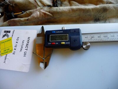
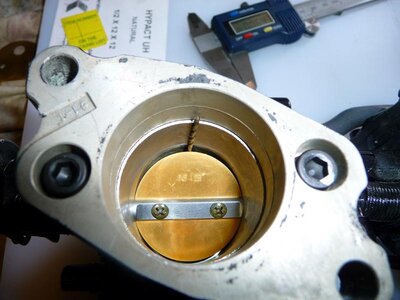
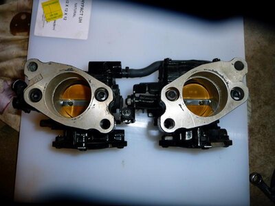
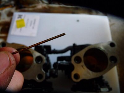
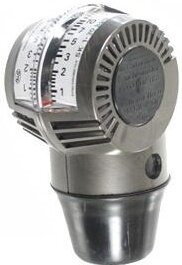
It's not a difficult process, but like every good job done, it just takes time. The first thing to do is keep the carburetors together and set the throttle butterfly side down on a flat surface. Then I had to find a small drill bit of about 0.060" or 1/16". I set the straight portion of the drill shank inside the throat of the lead carburetor (the one with the throttle cable linkage) in between the carburetor body and throttle butterfly. Then I closed the butterfly onto the drill bit shank and adjusted the idle set screw until there was just a very slight amount of drag against the the drill shank. With the second carb still linked together to the lead carb, I did the same with the drill bit and adjust the throttle linkage set screw to match the amount of drag put onto the first throttle butterfly. Now the throttle butterflies are synchronized. After installing new carburetor kits and re-installing the carburetors onto the intake manifold, the engine was the last part to be installed and off to the garden hose. Although I was not able to get and photos of the final synchronizing stage, it is still easy enough to explain. Once on the garden hose and running, I used a synchronizing meter to fine tune the last little bit of the carburetor setup phase. The top end adjustments can not be made this way, this is strictly for getting the butterflies working together properly and for setting up the idle circuit. With the flame arrestors removed and the engine running on the garden hose, I put the synchronizing meter into the mouth of the carburetors and checked to see which carb was drawing a higher airflow. The one with the higher flow rate was the one to be adjusted down by way of backing out the low speed mixture screw until the meter read to be about the same on both carburetors. Now the engine was ready for the water testing, one turn out on the high speed screw and take it for a ride, any hesitation and back out the high speed screw just a touch more until the hesitation is gone. What a ride, with the new pipe and rejetting, the ski performed well beyond expected. I'm looking forward to next Spring so I can install the trim system and add another through hull to bring back my auto bilge, a useful tool when electric pumps keep failing. Below are the photos of the synchronizing process and the German SK snail type synchrometer I used.
 

Attachments

  • Carbs 1.jpg
    Carbs 1.jpg
    52.6 KB · Views: 149
  • Carbs 2.jpg
    Carbs 2.jpg
    31.6 KB · Views: 141
  • Carbs 3.jpg
    Carbs 3.jpg
    56.5 KB · Views: 142
  • Carbs 4.jpg
    Carbs 4.jpg
    54.7 KB · Views: 144
  • STE-SK-2.jpg
    STE-SK-2.jpg
    18.5 KB · Views: 150
Last edited:
A few photos of the last little of bit of summer.
 

Attachments

  • August Jet Skiing 7.jpg
    August Jet Skiing 7.jpg
    71 KB · Views: 140
  • August Jet Skiing Pic.jpg
    August Jet Skiing Pic.jpg
    73.5 KB · Views: 156
  • August Jet Skiing 9.jpg
    August Jet Skiing 9.jpg
    70.5 KB · Views: 148
  • August Jet Skiing 8.jpg
    August Jet Skiing 8.jpg
    71.6 KB · Views: 143
  • August Jet Skiing 6.jpg
    August Jet Skiing 6.jpg
    72 KB · Views: 135
  • August Jet Skiing 5.jpg
    August Jet Skiing 5.jpg
    70.5 KB · Views: 142
  • August Jet Skiing 4.jpg
    August Jet Skiing 4.jpg
    71 KB · Views: 145
  • August Jet Skiing 3.jpg
    August Jet Skiing 3.jpg
    59.5 KB · Views: 140

TontoM3

Manager of Gnar Shredding activities
It is stuff like this that can keep my scratching my head for hours on end! Thanks for a simple solution to a common problem. To have the idle circulation properly adjusted is huge and a part that usually takes me a lot longer than I feel it should. Where do I get one of those meters?
 
There are several locations to buy this type of syncrometer, but most of them sell the Chinese version which look identical to the last detail but I have zero trust in them. The one I used belongs to my boss at work, his is a German made model. Here is the link where he bought his from (www.aircooled.net - see below). You can also hunt for it on Google but it seems that the only benefit would be maybe a place closer to where you live sells them and has them in stock, they seem to be consistently priced at about 50 bucks, just remember to only go for the German made model...

Google Search: German SK Model Snail Type Syncrometer Carb Sync Tool

http://vwparts.aircooled.net/Snail-Type-Syncrometer-Carb-Sync-Tool-GERMAN-SK-p/ste-sk.htm

Here is another location for you...

http://www.socalautoparts.com/index.php/tools-c-1204
 
Last edited:
Reed Stuffers - Update - July 11 2014

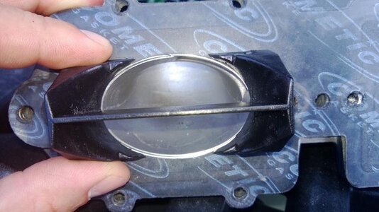
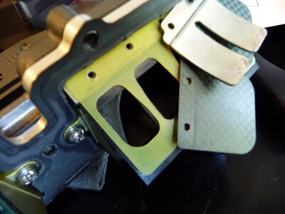
In a previous post, I mentioned my findings with a set of R&D reed cage stuffers. After reading a few very recent thread replies regarding these little contraptions, they reminded me of my most recent intake removal of just a few days ago. I thought I would give the ol' stuffers one more try at the start of the season when I was changing out my intake set-up to run my stock duals. Granted the performance of my ski was still quite good, I believe these little findings are worth mentioning. Currently, my ski has a set of Boyesen dual stage carbon fiber reeds. Interestingly, what I found with these reeds and how they work with the stuffers, is that due to the depth that the stuffers sit within the cages, it appears that the reeds are actually being obstructed by the stuffers.


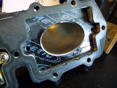
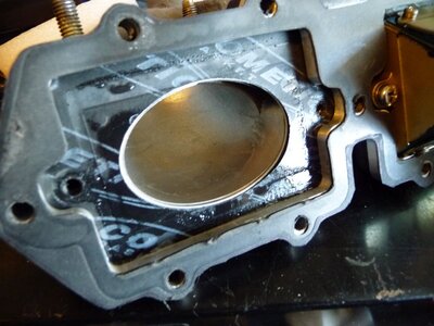
In the one photo, you will see that the outside portion on corner of the reed cage, about 50% of the reed window is obstructed by the stuffer. This is the same on all four corners of both cages. That equals a total loss of about four reeds worth of fuel/air flow. Granted my reeds are one piece covering two windows per half, but you can see just how much window gets blocked out by the stuffer. In the following two photos, you can see how the stuffers have collected some of the fuel/air charge to the extent that they have allowed it to accumulate and soak the gasket where the stuffers did not seal to the gasket. Even though the logo found its way to imprint in the gasket the stuffer bodies still did not fully seal...somewhat comical actually. But when looking at these photos, this has been the determining factor for me to say the stuffers are not benefiting my setup but rather hurting it by throwing off the carburetion/air flow due to accumulation and impedence. Once the new JetManiac Yamasaki coil arrives as the stock coil finally failed last weekend, I will be back to testing my set-up without the stuffers and offering my results. For now though, here is the photo evidence, something to consider if you are contemplating on trying them.
 

Attachments

  • P1010457.JPG
    P1010457.JPG
    90.4 KB · Views: 105
  • P1010458.JPG
    P1010458.JPG
    119.5 KB · Views: 100
  • P1010459.JPG
    P1010459.JPG
    116.7 KB · Views: 106
Last edited:
Hull Reinforcement: March 2015 - Re-Glassing

Quite a while back I did some beginner based/experience reinforcement fiberglass work to my engine compartment and repaired a breach in the hull. The breach occurred right where the battery is located and I am not convinced that the stock battery straps allow for too much movement of the battery allowing it to slam the inside of the engine compartment. This would be to me the catalyst for the initial hull breach and since has expanded further down the hull in both directions. Once I realized the new breach line in the black paint I decided that it was time to strip the hull down for a more extensive and proper reinforcement effort. As it was mentioned by Roseand, the fiberglass did not fair well. I used a Bondo automotive repair kit on my first attempt. At first it held up quite well but after a year of harsh water abuse it finally became more of a finished product out of the mould rather than a supportive addition.

This year the job was to remove the old glass, and change the approach to reinforce the engine compartment. In addition, since the hull had to be repaired as well, I have decided to move on from the black and green color combination to something different yet to be determined. One main reason for the decision to move on was for visibility reasons. Last year we had some great wave conditions and some great photography, but the photos were good evidence that the black colors were not overly visible even in bright sunshine on freshwater. If there were any cloudy days the ski became significantly harder to see in an already dark colored water. The photos had made the decision for me, time to move on to newer and brighter colors. On the plus side though, if anyone had concerns about using Rustoleum gloss black, I can vouch for it as being excellent for its ability to stay attached to the hull and looking great, even below the bond rail. In addition, when I painted the ski black, I did not use any primer, just went straight to painting it and it held up like an Ironwood tree against a chainsaw. On the opposite side of the spectrum, I used a clear coat meant for moisture and sunlight but it failed miserably. It was Minwax Helmsman Spar Urethane clear coat. I made sure to give it about 3 good thick coats when I applyied it, and then allowed it to cure for about 6 weeks before letting it have contact with the water. Once into the lake, it only took about 5 minutes and the clear coat sheeted off like a wet layer of plastic food wrap. I knew this happened after a quick 5 minute warm up run. When I returned to the ramp I saw what I thought was a large plastic bag floating around. I picked it up to throw it into the garbage when I noticed a chrome partial Super across it. That was the decal I put on the bottom and clear coated over top of.

This year, the new approach is 3 mat kits of Noah's 12oz x 50" 0/90 stitch mat biaxial glass cloth and securing it in place with East System epoxy resin and matching intermediate hardener. Because of the success I have had with the Rustoleum spray paints I will stay with using them but for the clear coat, this time around I am going to do it with a proper gel coat using Evercoat One Step Finish Gel-Kote. What I like about the one step gel coat is that there is no need for adding in hardeners, only needs a 10% volume equivalent mix of acetone and can be used in a sprayer, and when cured only needs a buffing to bring out the shine. This is because the wax mixed within surfaces after application and seals the gel coat for the curing phase.
 
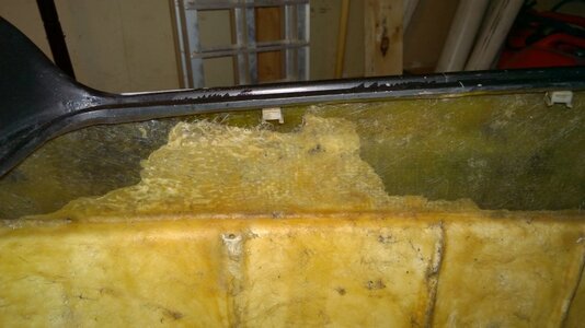
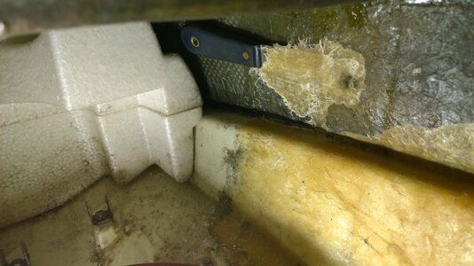
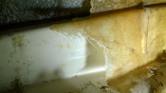
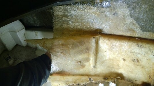
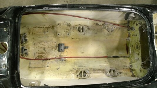
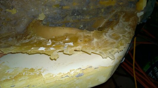
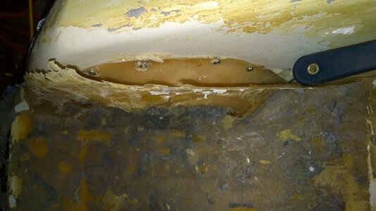
When I started this process, I thought much like the others that this was going to be a long and tedious job. My first area of importance was the engine compartment. Having the need to get that hull breach repaired, removal of the glass work done to the engine compartment was on the top of the list. I wanted to make way for the new glass kits before any other hull work. One nice thing about being a beginner to some of this work is that although in the end I have to re-do the work, the initial impact was minimal and easy to correct. With the Bondo fiberglass repair kit being made with polyester resin, the resin did not stick to any area of the hull or where it was applied, even with a well scuffed and prepared area. The glass came out of there with ease. All it required was a paint spreader, a short pry-bar, and a medium length pry-bar. Once the glass started to lift, it came out in less than an hour. You will see in the first photo how the glass had already began to lift from the hull. I used this to my advantage to complete the removal process. Once the old polyester resin glass was removed I went to work with a 4.5" grinder using a soft pad flap disc to remove all the ribs except the one on the right with the hole in it. I figure it serves a good purpose if not now, eventually so I chose to keep it. The rest of them were only going to impede a good mechanical bond between the new glass/resin application so I did away with them. This is something I should have done in the beginning but at the time I was hoping to keep them for added rigidity and flex resistance. Now, I will put my trust in quality glass and resin rather than the ribs which were basically just body filler. The SMC (sheet molded compound), is much more like body filler and will sand off with ease. When doing this work though my first priority was to get a proper breathing mask with replaceable filter cartridges. This powdery substance is not something I want being filtered into me.
 

Attachments

  • WP_20150311_001.jpg
    WP_20150311_001.jpg
    92.8 KB · Views: 88
  • WP_20150311_002.jpg
    WP_20150311_002.jpg
    96.5 KB · Views: 81
  • WP_20150311_006.jpg
    WP_20150311_006.jpg
    70.4 KB · Views: 80
  • WP_20150311_007.jpg
    WP_20150311_007.jpg
    99.6 KB · Views: 79
  • WP_20150314_007.jpg
    WP_20150314_007.jpg
    98.8 KB · Views: 80
  • WP_20150314_010.jpg
    WP_20150314_010.jpg
    106.6 KB · Views: 80
Last edited:
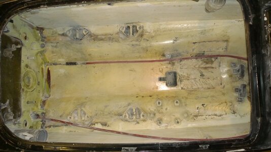
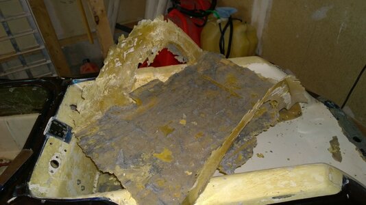
After I had cleared out the engine compartment and prepared it for reinforcement, the thought had occurred to me that my hulls has what I thought to be a small leak. I knew it was at the left rear corner where it appeared that some of the original manufacturing adhesive in between the bond rail was missing. Once I thought about that and how the engine bay glass had lifted so easily, I started to wonder how well my foot holds were fairing. They were glassed in with the same Bondo grade materials but a year prior to the engine bay. I knew my turf kit was starting to look a little old and dirty, the foot hold area was turfed quickly with patches to fill in the open areas of the foot holds where the pre-cut kit had too much turf removed to make way for the Blowsion brand holds. As well the soft under-padding was starting to remain compressed and leaving sunken in outlines of where my feet usually were. So I decided to get rid of the old turf kit and prep the tray for new turf. Once I removed the turf and checked the glass work it was just as I had thought, the floor under the glass work would move up and down and the glass would stay in place. Using the method to remove the glass from the engine compartment I did the same to the tray. It was actually a neat experiment because it proved to me that if I wanted to make my own bottom deck, I could use my ski as the mould. Since the polyester resin does not stick to this hull at all, I could make my shell and have a rather solid one at half the weight. I managed to remove the foot hold glass work in one piece in about 15 minutes...not bad.
 

Attachments

  • WP_20150312_001.jpg
    WP_20150312_001.jpg
    82.2 KB · Views: 79
  • WP_20150312_002.jpg
    WP_20150312_002.jpg
    80.8 KB · Views: 80
  • WP_20150312_003.jpg
    WP_20150312_003.jpg
    97.9 KB · Views: 74
Last edited:
Top Bottom