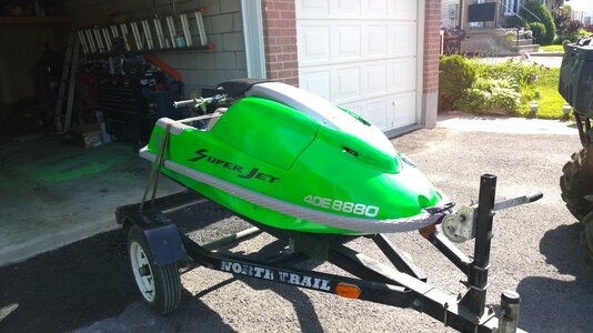
Super Jet 1996 Round Nose SuperJet Project

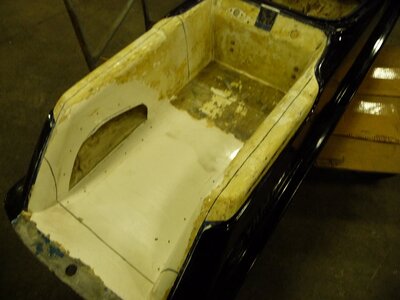
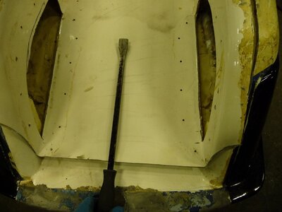
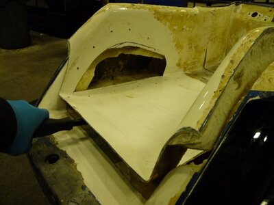
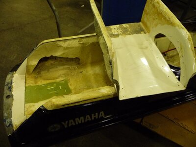
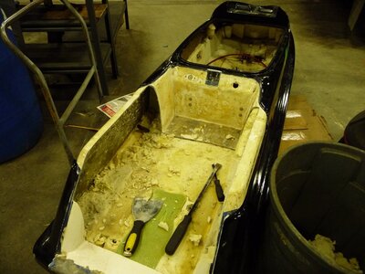
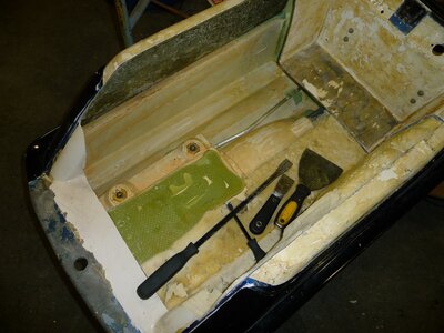
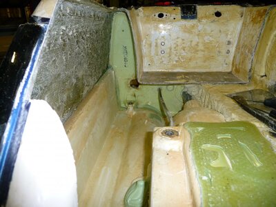
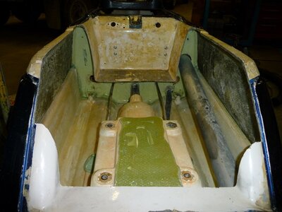
With the tray clean and free for removal, it was time to start cutting into it and get it out of there. I used my trusty Dremel with the cut-off fiber discs. I was expecting to go through a bunch of them but it actually only took 3 discs to go the full distance around the tray. Once cut, the pry-bars became the tool of the day. With light pressure in various spots the tray lifted out. It was much like when I removed the cut-outs for the foot holds. A little prying behind the areas being worked, and there was a sound like it was tearing fabric as the tray was being released from grip of the foam. Fortunately for me, the SMC also does not like having foam stick to it.
 

Attachments

  • P1010475.JPG
    P1010475.JPG
    91.2 KB · Views: 174
  • P1010476.JPG
    P1010476.JPG
    78.1 KB · Views: 164
  • P1010477.JPG
    P1010477.JPG
    108.8 KB · Views: 160
  • P1010478.JPG
    P1010478.JPG
    93.6 KB · Views: 161
  • P1010479.JPG
    P1010479.JPG
    92.7 KB · Views: 164
  • P1010480.JPG
    P1010480.JPG
    107.9 KB · Views: 163
  • P1010481.JPG
    P1010481.JPG
    113.6 KB · Views: 162
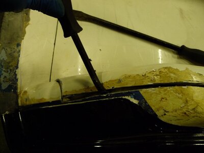
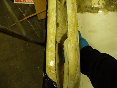
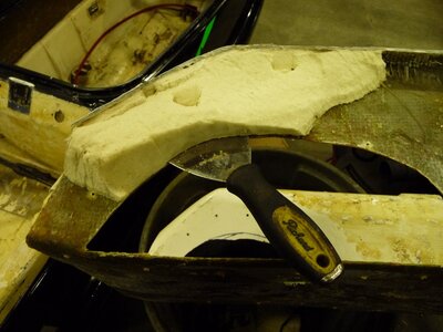
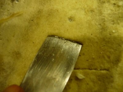
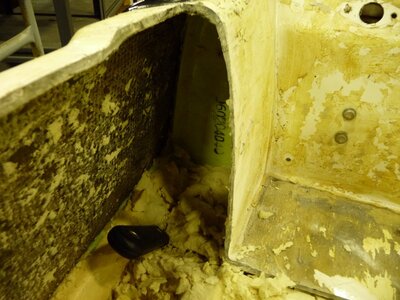
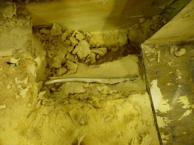
The last step to the process for now was to remove the soaked foam. When I started into it the foam felt damp but not soaked. The further I dug however, the more concentrated the water. In the first photo the water accumulation was evident by the glossy line covering the spreader blade. As mentioned, the SMC does not like very much of anything sticking to it, this foam was no different. Using a wide blade spreader and on occasion a narrow blade one, the foam removed relatively easily. The areas that were more work however were where there was the most density such as in between the gunwales and pump area. The way I removed it was by stuffing the spreader blade straight down into the foam as if I were trying to cut a slice of cake. Then I would use the pry-bars, whichever one I decided to use at that time, usually the longer one, and popped out little cubes of wet foam. I tried to clean up as much of the foam as I could. At the end of the foam removal, it amounted to 2 big plastic garbage cans worth of foam. At the moment this is where I have made it to, the good part though is that it has only been a total of about one and a half weeks worth of work invested for everything done, engine removal, handle pole removal, wiring and foam removal.

One thing I will remember if I ever do this for anyone else, pay close attention to immediately beside the pump area. I had totally forgotten about the water lines running from the pump to the engine bay. Although I did not do much damage to the aluminum line, I did bend it and pull it out of the sealant. This is not much of an issue for me though as I plan to install 2 more tubes made of stainless, one for true dual cooling, one for bringing back the stock syphon bilge. I will also be adding in 2 Versiplugs and will still be using the electric bilge. This should allow the ski to collect lots of water and clear it out very rapidly. I will also be leaving the two large holes in the engine compartment open, the ones that Yamaha covered with stickers when they sprayed in the 2 part expanding foam. My reason for this is that it will allow some air flow to pass through the hull when trailered and help to keep things from going moldy and staying wet. When the ball in the Versiplugs are not being pushed against their seal seat, they are left open to allow air in, the open engine bay holes will help to carry that air through and keep things dry.
 

Attachments

  • P1010483.JPG
    P1010483.JPG
    80.1 KB · Views: 159
  • P1010484.JPG
    P1010484.JPG
    139.4 KB · Views: 158
  • P1010485.JPG
    P1010485.JPG
    135.4 KB · Views: 161
  • P1010487.JPG
    P1010487.JPG
    132.3 KB · Views: 160
  • P1010490.JPG
    P1010490.JPG
    137.3 KB · Views: 164
  • P1010491.JPG
    P1010491.JPG
    144.6 KB · Views: 161
  • P1010492.JPG
    P1010492.JPG
    124.4 KB · Views: 165
During the course of the week I decided that while waiting for the rest of my fiberglass items to arrive I would try my hand at making a bilge bracket. Currently I am still waiting on my biaxial glass mat and my Tom21 bolt on front sponsons. I have to say my hat is off to Tom21, such a great guy to deal with, just that alone makes me anxiously await the new additions to my hull. My many thanks Tom =)

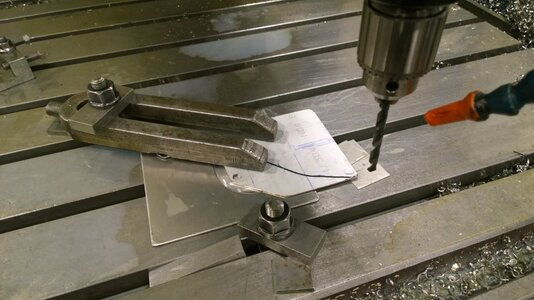
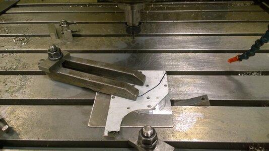
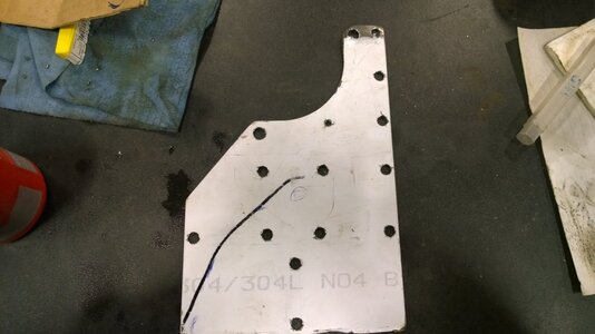
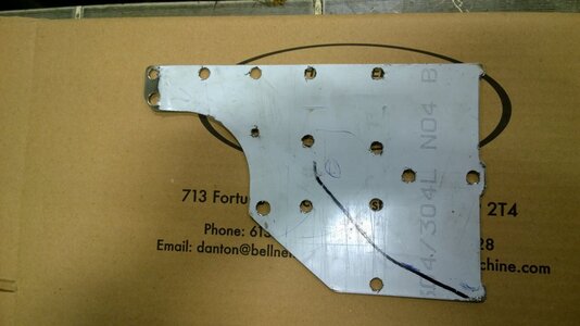
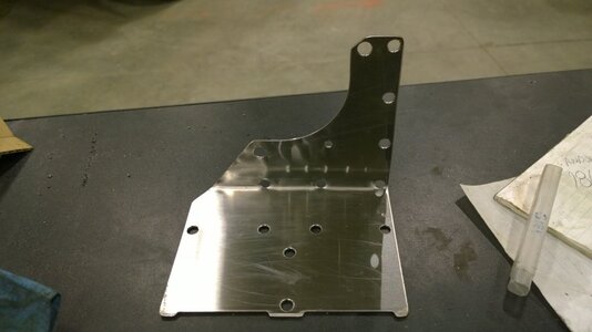
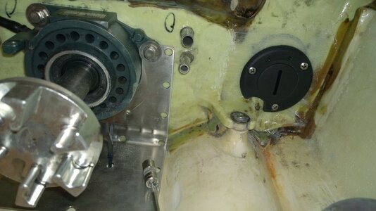
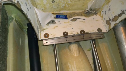
For my bilge bracket, I wanted to make it as feature filled for my needs as possible. With that in mind, I decided that I would change the approach for how my electric bilge will be secured to it along with my dual stock siphon bilges. Additionally, I made the bracket capable of accepting a second electric bilge pump should I need one, which I may just install anyway for additional piece of mind knowing that should one quit working, there will be a secondary on a separate outbound hose. This way there will be no mistaking if one pump has failed. My method for securing the parts will be by way of tie-straps only. I have seen on many occasions bilge pumps secured by only the four little screws going up into the filter base which eventually breaks. The only way I like to see an item with top heavy weight such as these little pumps is to have the securing locations wrap over the top of them. The idea here is to have the tie-straps secure the pump by way of crossing over the pump in an X pattern. For this, I drilled 4 holes just on the outside edge of the filter diameter, one set of holes per pump location. There were some miscalculations in the math when figuring out the plate bending so the four holes at the corner of the bend are little high into the bend. But I did a dry run test fitment and I figure it will still work out, everything will just be moved forward about 1/4 of an inch or so, not a write off but not exactly as planned. In addition to the mounts for the electric pumps, I also notched out two locations for tie-straps to seat into when mounting the dual siphon bilge boxes. This should help keep the straps from sliding off of the plate, well, more so if the bending phase was figured out correctly. Likewise though, there are two holes in the middle of the plate between where the siphon bilges will get mounted. This will allow me to secure the siphons across the length as well, should be no movement there. When I bent the plate, I wanted to keep it about 1/16 of an inch off of the hull floor. This way I would still be able to slide replacement tie-straps under if one were to break. Going up the side of bracket I added three additional holes for securing things to. It seems I am always looking for locations to tie-strap things to, this will help out quite a bit when isolating the electric bilge harness and siphon hose for the one side. As for material, we had a piece of nice 304 stainless steel plate at work as a cut-off so I was able to use that. It required a 4 inch milling cutter to do a clean job but that was all it needed. The cutter did a great job and the diameter is pretty well exactly the size of the midshaft housing. If there are no glass parts in the mail for me tomorrow then this weekend might see the start of some engine work until the glass comes in.
 

Attachments

  • WP_20150329_005.jpg
    WP_20150329_005.jpg
    106.3 KB · Views: 163
  • WP_20150329_006.jpg
    WP_20150329_006.jpg
    112.8 KB · Views: 162
  • WP_20150329_007.jpg
    WP_20150329_007.jpg
    84.3 KB · Views: 155
  • WP_20150329_008.jpg
    WP_20150329_008.jpg
    76.6 KB · Views: 157
  • WP_20150329_009.jpg
    WP_20150329_009.jpg
    68.7 KB · Views: 162
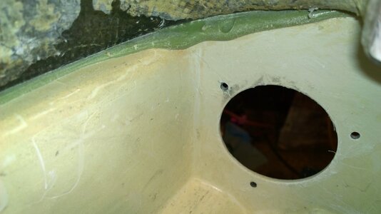
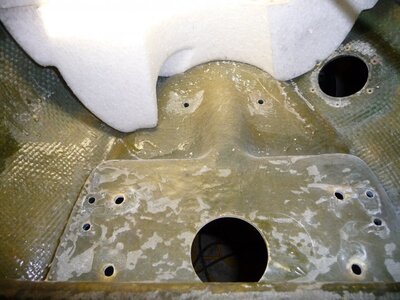
It has been about a month and finally my fiberglass has arrived. After having a second look at the hull I decided that there was still more preparation work to do. With the 100 grit sandpaper in hand I took to refining the last elements of the engine bay. One area that kept my mind busy was the exhaust outlet. I debated how to go about installing my new Versiplugs for quite sometime now finally deciding on just slightly raising the exhaust outlet hole by about an eighth inch. This allows me to move the tube up only very slightly while allowing just enough room to install one of the two Versiplugs under the outlet. I also noticed a new hull fracture. It stems out from the exhaust outlet hole and under the right rear of the bond rail. Looks like more glass work for me.
 

Attachments

  • WP_20150418_007.jpg
    WP_20150418_007.jpg
    70.3 KB · Views: 147
  • WP_20150418_008.jpg
    WP_20150418_008.jpg
    55.6 KB · Views: 145
Last edited:
Finally after a repeat cold spell, this week has turned around regarding the weather. Back into the sunshine and well into the plus degrees. At first I hesitated to get into the glass work as I was not only lazy but really not in the mood to fool with glass again. I am glad that I decided to get back into it though, now the hard part is over with and I can move onto easier and quicker work.

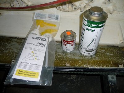
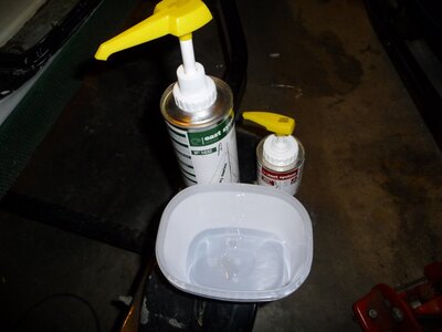
The first thing I chose to do this time after buying all of the appropriate and good quality repair items, was to set up my resin and hardener pumps. These pumps are calibrated to mix the appropriate ratios per pump. The only thing I had to do was shorten the pickup tube on the resin to work in the bottle size I have. There are two hardener pumps, one for intermediate curing speed hardener, and one for fast. I used intermediate so I would have plenty of time to work the glass and get as much of the air out from underneath it as possible while laying it up. The East System resin and hardener mixes at the same ratios as the West System so I didn't have to worry about improper mixing.

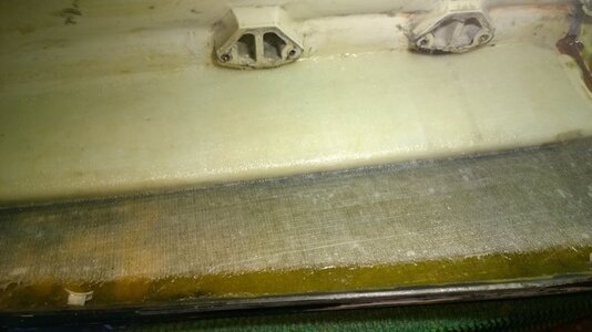
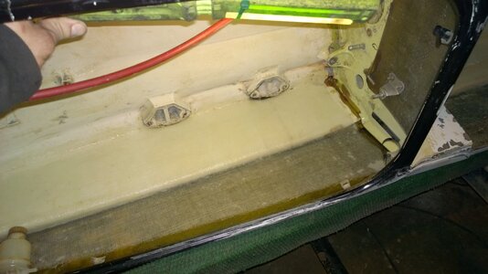
After priming the pumps to prevent improper mixing on the first shot, I mixed up three pumps of each, resin and hardener. I then used that as a combination of filler and sealer for the bond line. I could have used microbubble filler to expand the range of coverage for the resin mix but that could have impacted the resin's ability to seep into the bond rail where the hull breach was leaking. Then I applied my glass and worked it in. It took about 2 hours per engine compartment side to really work the glass in while working the air out. While applying the resin, I found that just spreading a normal pass with the paint brush and not focusing on one area gave the resin time to absorb into the glass. So far I have only used about 7/8 of my first tin of resin and hardener. When the resin became more tacky and not so smooth and free to move the glass around, I started applying pressure to the brush. While holding the glass in place tightly to the bond crevasse with a half sized paint mixing stick, I would push down on the brush and push the air toward the bottom of the deck forcing out any pockets. I kept doing this until I was comfortable enough with the level of cure in the resin. I found that when the glass stopped responding to the brush pressure for the most part, then it was safe to leave it for the night without fear of any further lifting or air pockets developing.
 

Attachments

  • WP_20150428_001.jpg
    WP_20150428_001.jpg
    89.5 KB · Views: 137
  • WP_20150428_003.jpg
    WP_20150428_003.jpg
    89.1 KB · Views: 135
  • P1010512.JPG
    P1010512.JPG
    133.3 KB · Views: 115
  • P1010515.JPG
    P1010515.JPG
    76 KB · Views: 117
It has been a good while since I have updated my thread here so tonight is the night. Unfortunately things have been a little on the excessively stressful side lately and I have not exactly been my usual self. Not too long ago a very dear relative of mine lost his house to a field fire. The wind picked up quite heavily without any hint of a warning and sent the path of the fire directly into his house. He lost everything including 2 generations of memories. It has been a trying last few weeks to say the least. There is only so much a person can do before they have to come home and remember what has to be done at home too so here I am trying to catch up.

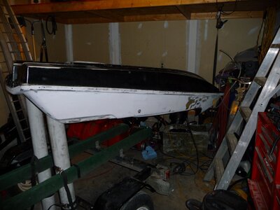
In my last posting I mentioned working with the glass and using the resin and hardener through calibrated pumps. I updated that posting with a pair of photos showing the mixing pumps and how they are used. It's a great idea because it really does maximize the life span of each can's contents not over mixing or under mixing, and the results are always consistent so the strength to mix ratio should be at about the optimal it can get. Since then, I have moved the exhaust exit up about a half an inch from its original position allowing me to install a Versiplug underneath of it. I chose to install two Versiplugs, one in each side of the hull in an effort to eliminate any further chances of having water stay held inside the hull. Prior to removing the soaked and semi-frozen foam, it was all I could do to lift and move the hull around without the engine or bolt on hardware still attached. Now, I can move the hull around on my own...on a good day...and be able to do the work I need to on it. When doing the exhaust relocation I decided to stand the hull up on its tail end in an effort to keep the glass as flat as possible while I set it up for not only the exhaust, but to also reinforce the area around the exhaust outlet hole. I found that area was cracking as well and working its way up into the bondrail just like the first hull breach did. I also left the ski standing up on the tail end while I reinforced where my new one way valve was going in.

I also turned the hull upside down to again keep a flat working surface while I added a couple of reinforcing layers of glass to the handlepole bracket area.
 

Attachments

  • P1010526.JPG
    P1010526.JPG
    111.4 KB · Views: 120
  • P1010529.JPG
    P1010529.JPG
    142.9 KB · Views: 121
While setting up for the new one way valve kit, I also decided to go ahead with adding in three cooling supply lines and having a fourth line running to the stock siphon bilge. I want to make absolutely certain that I am getting the most water out of my engine bay as possible. I figure between the electric 800 gph bilge, on an electronic WaterWitch control module, with dual siphon bilges and a quick draining one way valve kit, there should not be any more issues with excessive water in the engine bay. Also, having dual Versiplugs installed should be the last detail needed to keep the rest of the hull free from water weight regardless of any leaks.

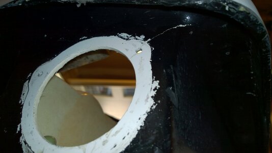
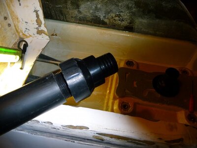
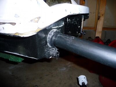
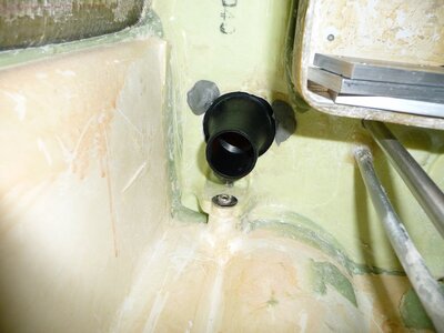
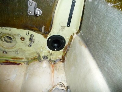
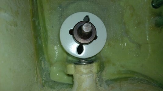
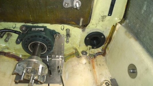
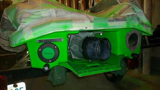
Once the motivation set in, I began working on the one way valve kit. The first thing I did was research the idea and get some knowledge of whether it is a worth while thing to do or not. The next thing was to determine what the draw backs could be and so far it seem that the worst fear is replacement should the valve fail. Keeping that in mind, I decided that while having my hull stripped I would try to come up with a way to make my valve kit removable. What I ended up doing was getting a 1.5" I.D. PVC pipe, threaded it and screwed in a 1.5" one way valve with a body diameter of 2 inches O.D. It had little plastic bars on the O.D. going with the length of it, I assume to aid in gripping it while twisting to thread it into place, and so I took to the file and cleaned those off. Doing this allowed me to get the O.D. down to just a shade under 2 inches allowing me to install the entire kit through the back of the hull. This worked out well as I needed to use a 2 inch hole saw to install the flanges for the drain kit. Originally I wanted to be able to remove it all from inside the engine compartment but with the way the valve is designed, in order for it to seal water out and still work with the kit I put together, the valve had to be installed toward the transom. I thought about trying to keep the price down but I also wanted to keep the intention of making it replaceable a priority so the kit ended up costing a total of about 30 dollars. The expensive portion was the flange portions being $10 for one, and $13 for the other. The flanges I used were purchased from our local marine specialty store called Marine Outfitters. But I would assume these can be had at many other places such as West Marine. The flanges are actually filler spouts for water, gas, or diesel. The nice thing about them is that they also come with a thread-in plug. If at any point in time the one way valve fails, I can just thread in one of the plugs and continue the ride without any concerns. One other thing I took into consideration was the the angle that the transom has. It would have been a chore to try and fit those flanges in without the use of the clear braided hose. That hose is surprisingly strong and has just the right amount of arch to it to work with the odd angle the transom as and line up to the flange just nicely.
 

Attachments

  • P1010542.JPG
    P1010542.JPG
    105.8 KB · Views: 121
  • P1010543.JPG
    P1010543.JPG
    101.1 KB · Views: 121
  • P1010548.JPG
    P1010548.JPG
    109 KB · Views: 122
  • P1010549.JPG
    P1010549.JPG
    132.7 KB · Views: 123
  • WP_20150518_005[1].jpg
    WP_20150518_005[1].jpg
    89.8 KB · Views: 124
Last edited:
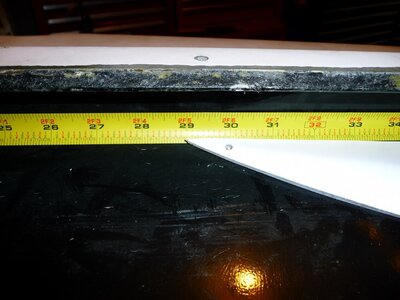
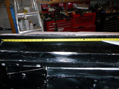
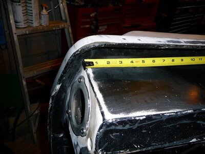
Finally for this weekend, the Tom21 front sponsons. I researched this one for a good long time as well, first to determine if they were something I really did want and could benefit from, but also just over the last week or so just trying to figure out how to install them properly. After reading the very rare bit of information here and there I decided to not only send in a question to Tom, but to also just go with my gut and start somewhere while waiting for the response. It took only about a half an hour to hear back from Tom but fortunately for me he confirmed that the location I am going with looks good. One thing I did read about was the location height of sponsons, if they are flush to the bottom contour lines of the hull the chance of a scary high speed run is there. So I chose to mount mine up snug to the bondrail and measuring from the transom, 29 inches forward which would be where the little trailing edge of the sponsons would line up to. This worked out well as it seems 29 inches is just right for how I wanted to mount them. It puts the sponsons far enough forward but also keeps them about half an inch higher than the bottom contour line of the hull. Tom suggested keeping them about a half an inch away from the bottom lines as well so I was right on track with his recommendations.
 

Attachments

  • P1010559.JPG
    P1010559.JPG
    112.9 KB · Views: 122
  • P1010560.JPG
    P1010560.JPG
    158.3 KB · Views: 121
  • P1010562.JPG
    P1010562.JPG
    131.8 KB · Views: 126
  • WP_20150524_001[1].jpg
    WP_20150524_001[1].jpg
    69.8 KB · Views: 122
Build looks good but that one way valve in engine bay is pretty high in bulk head, it's not going to drain much water...usually the hole is almost laying on the engine bay bottom...I'd drop it down if you can
 
Thanks for the suggestion jet, I wondered about that a little bit but I also figured that it will be mainly for when I am doing subs, stabs, and fountains and really filling the engine bay. Basically it's just to insure that the water level can't get higher then that. I did look at going lower but had a hard time trying to figure out how I would be able to use the flange and stay close to the floor so I went with the best that I could do. Ah well, between the dual siphon bilges and electric bilge it will have to be better then last year having to rely on only one electric bilge entirely :) I also wired in a digital sensor switch to the bilge so if the level gets up to a certain point the bilge automatically kicks in without needing my attention. I do have a switch wired in as well and have had to use it hehe. Also I feel like I am so far behind on this build now that I just want to get it over with. I had intentions of doing a bunch of new engine mod work but I am going to postpone that until next year now. I did get a few things done, but the season is pretty well here now and I just want my ski ready to go again. The Tom21 front sponsons were installed fully last night and the bottom deck I have just finished painting and clear coating tonight. Now it gets to stay put for a few days upside down to allow the clear coat to fully cure. I have to glass in the tray still so I might look at that drain location again, one thing I did have in mind about keeping it a little on the higher side was if any screws or something like that fell off, it would stand a better chance of not getting lost in the lake through the drain tube. I found a little screw in there when I started removing the engine, still trying to figure out where it came from lol. But it is nice to know that I won't lose that stuff.
 
I just took a second look at that, you're right I should try to get it lower. I might have to rework that concept, thank you sir. It's amazing how accepting a person becomes when they are so tired that they should sleep for a week to recharge, I mulled over that kit for about 2 weeks trying to figure out the cleanest way to do it lol. I stayed up so many nights maybe getting 15 minutes of work done out of 4 hours of looking at it, I just kept telling myself it is still 15 minutes further along the build then 15 minutes ago :D I watched that series of Alaskan Bush People, and like the line the father said, if you worked all day and only gained an inch, well hey, that's an inch further then before. I just need to stay positive and focused.
 
Last edited:
I took your suggestion to heart jetx and lowered my quick drain flange as low as I could get it without cutting off the posts with the stainless screws. Now my quick drain is only a few inches higher than the lowest spot of my engine bay. I figure whatever doesn't find its way out through the drain, will get picked up by the siphon bilge, or electric if it becomes needed. Now I am ready to put my tray back together and really see the end of the project for this year, and the thread in plugs will help insure a good water tight hull if the one way valve fails. One plug for each end of the drain kit. All I need now is a yellow float fob on the end of the ball chain on both plugs, that way losing one should never be an issue.
 

Attachments

  • WP_20150602_012.jpg
    WP_20150602_012.jpg
    62.2 KB · Views: 101
  • WP_20150602_013.jpg
    WP_20150602_013.jpg
    98.7 KB · Views: 99
  • WP_20150602_014.jpg
    WP_20150602_014.jpg
    92 KB · Views: 98
  • WP_20150602_016.jpg
    WP_20150602_016.jpg
    87.6 KB · Views: 98
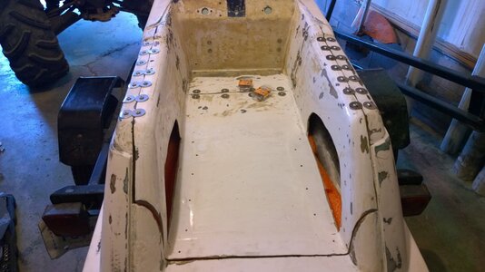
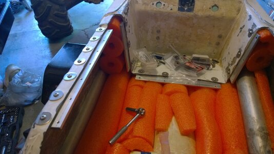
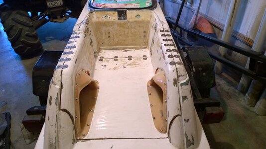
With all the engine compartment and hull repair work done, it was time to start the rebuilding phase. For the tray, I used aluminum flat bars a quarter inch thick, drilled and tapped 1/4-20 for the front and up the inside walls of the tray. For the the tops of the gun whales I went narrower and used 10-24 stainless fasteners to help keep the strength and alignment in good order.

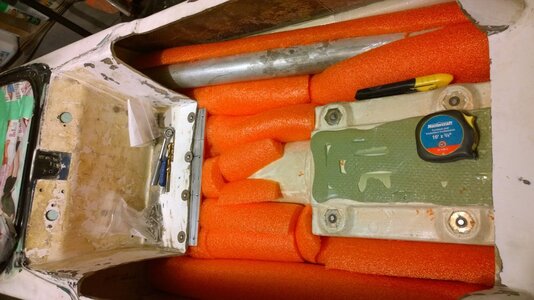
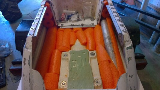
Next was the floatation foam. I didn't like the mess of the two part foam so I did some research, made a phone call and decided that poole noodles were a good choice. In fact, a local fire and rescue boat builder here in town told me that whenever they work on emergency services boats they quite often find bags upon bags of noodles in between the hull decks. He did a quick calculation for me and figured it would take 10 noodles at 3.5" diameter to reach a positive buoyancy for a 300lb ski. That would mean the ski needs about 5 cubic feet of foam if I remember correctly. I made sure to jam as much in there as I could as well as in behind and all around the footholds. 6 1/2 noodles was the best I could do...not bad.
 

Attachments

  • WP_20150602_021.jpg
    WP_20150602_021.jpg
    88.5 KB · Views: 92
  • WP_20150602_025.jpg
    WP_20150602_025.jpg
    123.7 KB · Views: 93
  • WP_20150603_003.jpg
    WP_20150603_003.jpg
    110.8 KB · Views: 93
  • WP_20150603_004.jpg
    WP_20150603_004.jpg
    96.4 KB · Views: 90
  • WP_20150603_001.jpg
    WP_20150603_001.jpg
    101.5 KB · Views: 88
  • WP_20150603_005.jpg
    WP_20150603_005.jpg
    98.1 KB · Views: 92
Last edited:
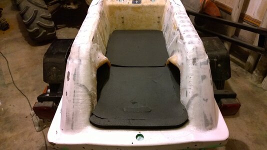
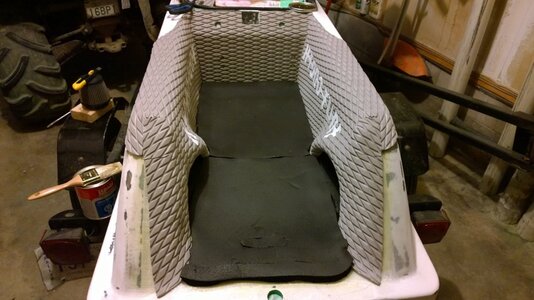
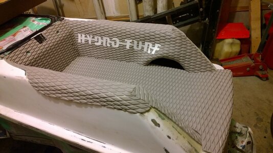
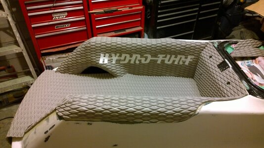
With the tray glassed in and trimmed clean, it was time to start working on the turf. Instead of the thin under padding they supply with a Hydroturf kit, I chose to go with a full one inch antifatigue kneeling pad. The footholds also were given a proper padding this year too. I don't like how that thin padding supplied with the kit remains flat after so many uses.
 

Attachments

  • WP_20150606_002.jpg
    WP_20150606_002.jpg
    90.2 KB · Views: 93
  • WP_20150606_004.jpg
    WP_20150606_004.jpg
    108.6 KB · Views: 97
  • WP_20150607_002.jpg
    WP_20150607_002.jpg
    115.3 KB · Views: 93
  • WP_20150607_003.jpg
    WP_20150607_003.jpg
    118 KB · Views: 91
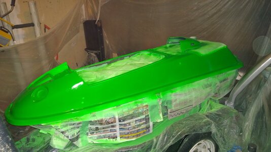
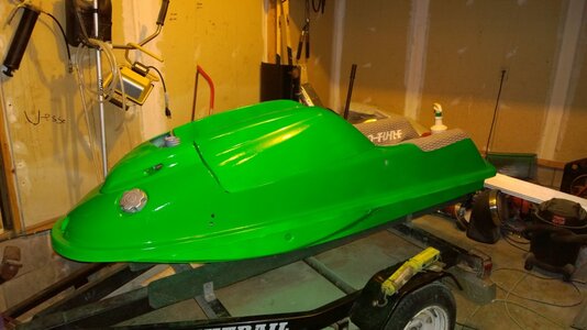
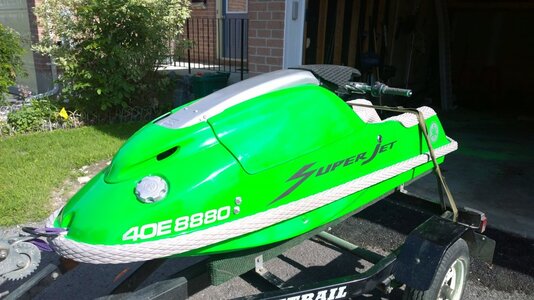
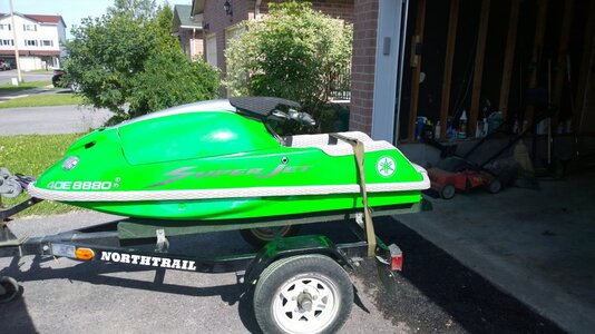
Finally it was time to finish giving it some color. I have always liked that Spring time green. The last little touches were just a few decals.
 

Attachments

  • WP_20150609_002.jpg
    WP_20150609_002.jpg
    96.4 KB · Views: 92
  • WP_20150612_003.jpg
    WP_20150612_003.jpg
    91 KB · Views: 96
  • WP_20150617_001.jpg
    WP_20150617_001.jpg
    134.4 KB · Views: 94
  • WP_20150617_002.jpg
    WP_20150617_002.jpg
    140.5 KB · Views: 95
  • WP_20150617_003.jpg
    WP_20150617_003.jpg
    133.8 KB · Views: 95
AC Racing Handle Pole & Blowsion Heavy Duty Spring

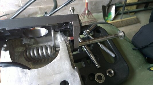
I have this pole and spring combo and the first time I installed it I found it to be of substantial difficulty to install. So I decided to go back to the stock pole and bracket as it was designed to just work with minimal install time and effort. After doing so and going for a ride I found that I actually had become used to the shorter AC pole and have come to prefer it. So I went back to that arrangement. But while looking at it I found what I would believe to be the easiest, fastest, most efficient way to install this combo. The bracket I am using is a Blowsion lowered single tube bracket. Because it is lowered, to install the pivot bolt you need to have the bracket loose with the nylon locking nuts just started on the threads.

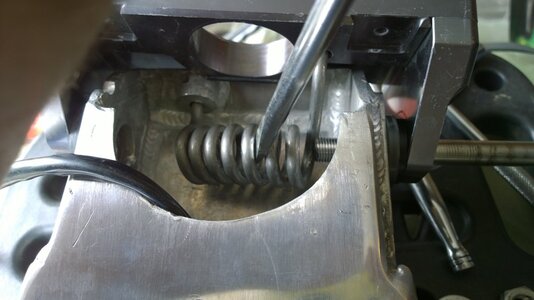
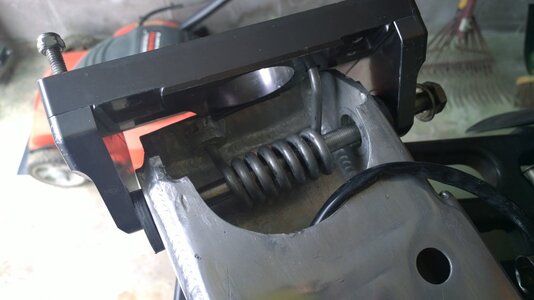
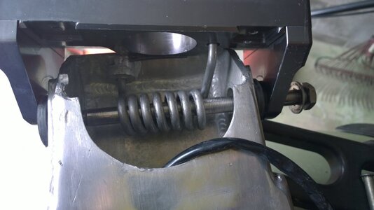
The last time I installed this setup, it took me about 5 hours and much fighting to get it into place. This time around I decided to document the process hoping to help out anyone that buys these parts, or even just the spring. I have read many reviews about the aggravation people are going through trying to install these so here is how I did it. First, remove your fuel tank, run the fuel out of it, or siphon it, either way empty the tank and remove it. Also remove the tank strap locking bracket bolted to the bottom of the engine compartment, this will really help with the removal process. Remove your cables and wiring harness from inside the stock pole and either let it hang over the side or tuck it into the hull. Remove the stock pole and bracket. Now with the new lowered bracket and after market pole, situate the spring as it should be inside the pole and bracket but don't worry about the pivot bolt yet. Just get your spring, bracket and pole ready. Now, using a plastic hammer and a large flat blade screw driver you will slowly work the bolt into place. Get the bolt started in,with a small amount of pressure you will use the flat screw driver to flex the spring just enough to tap the bolt inside the coils. Keep tapping until the bolt stops moving.
 

Attachments

  • WP_20150621_001.jpg
    WP_20150621_001.jpg
    83.4 KB · Views: 90
  • WP_20150621_002.jpg
    WP_20150621_002.jpg
    79.8 KB · Views: 87
  • WP_20150621_003.jpg
    WP_20150621_003.jpg
    72 KB · Views: 85
Last edited:
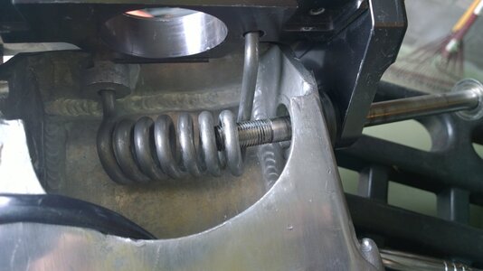
Using the same method, put the flat screw driver into the next coil and flex it in line with the bolt, then tap the bolt into that coil. Keep doing this with only one coil at a time, flat driver in, flex, tap through, repeat. Eventually you will get the bolt all the way through to the bracket, but the bracket and pole will still be offset. At that point, it is time to mount the pole and bracket assembly onto the top deck.
 

Attachments

  • WP_20150621_004.jpg
    WP_20150621_004.jpg
    67.7 KB · Views: 86
  • WP_20150621_005.jpg
    WP_20150621_005.jpg
    70.4 KB · Views: 88
  • WP_20150621_006.jpg
    WP_20150621_006.jpg
    86.3 KB · Views: 89
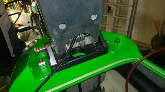
Once you have the threaded rods down into the holes, install the nylon locking nuts just until they stop turning by your finger strength. You will need the bracket to stay up high off of the top deck to finish threading the pivot bolt through. Once the bracket is in place as mentioned, you can now use the pole for leverage to shift it into alignment with the other hole and tap the bolt just a few times to get it seated with the threads in the bracket. Once seated, using your ratchet and 22mm socket on a short extension, start threading the bolt the rest of the way through, you may need to shift the pole around a little bit to help with the threading. That's it, you're done. Put the washer and nut onto the bolt, secure the bracket to the top deck, get your cables back into place and run them up into the pole if you did not choose to do it before mounting the bracket, reinstall the fuel tank, tank strap bracket and nose cover and set up your cables and wiring harness. My total install time was about 45 minutes for everything. 15 for the spring with the bolt fully through into the pole and bracket, 15 minutes to remove, reinstall and set up the cables and harnesses, 15 minutes to remove and reinstall the fuel tank. I hope this helps.
 

Attachments

  • WP_20150621_007.jpg
    WP_20150621_007.jpg
    87.2 KB · Views: 88
  • WP_20150621_008.jpg
    WP_20150621_008.jpg
    73.5 KB · Views: 91
Last edited:
I just wanted to do a little update to this thread in regards to an issue I have been dealing with since I bought my ski. All this time I thought my ski ran great and what I was getting out of it, albeit reasonably strong, was all I would get out of it. So over the course of last season I started encountering issues with what sounded like hitting the rev limiter. Eventually my coil died and failed to pass the multimeter tests. So that was replaced with a JetManiac Yamasaki coil. The ski ran quite well after that for the rest of the season but I still found the slight rev limiter issue. So I changed the pump seal and that brought back the proper engine load and no more rev limiter issues...for now. Well, this year, only a few rides out and the rev limiter issue started to surface again. I tried everything I could thinking that it was carburetor related. I changed the pop off pressures 3 times, each with the same results but the lower the pop off, the worse the running condition. Finally the running condition degraded to such a point that when I would try to rev up the engine while the ski was on the trailer I would see fire coming back up the intake manifold and through the bottom of the carbs. Once I saw the flames I knew the problem was not carb related anymore, it was strictly electrical/timing related. There were three possible scenarios to this, CDI, stator, or stator plate became loose and moved off of the timing marks. Well, I tested the stator with the multimeter and it passed with flying colors, right in the middle of the specs. So having a space CDI as a backup I thought I might as well try it. Put the ski back together, fired it up and revved it, no fire coming up the intake. I took the ski to the lake and sure enough the old CDI was done. The funny thing is, this issue has been haunting me here and there since I bought the ski 3 years ago. The performance of the ski now compared to when it ran the best I thought it had, is so far beyond different, it is indescribable. The ski now has easily 3 times more power than it ever had and no more rev limiter issues. The CDI cured the issues entirely. I read so many threads saying it most likely is a stator that I was expecting to have my ski down for a couple of weeks at minimum. But nope, a couple of hours after work, one replaced CDI and the ski is just a monster now. This makes me one happy camper, I hope this helps someone someday.
 
Wow, I can't believe it has been 2 years ago since my last entry. Most of my work since then has mainly been maintenance lol. There is so much a person can tell right now. At this moment though because I am quite exhausted I will just put this up there...
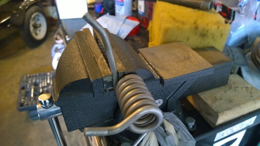
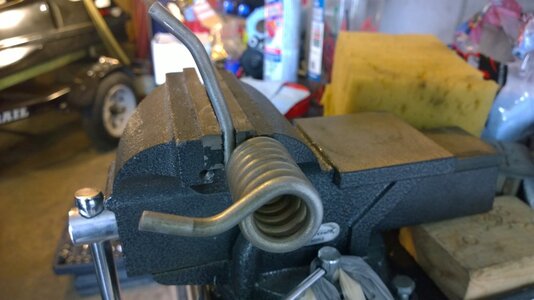
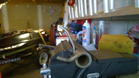
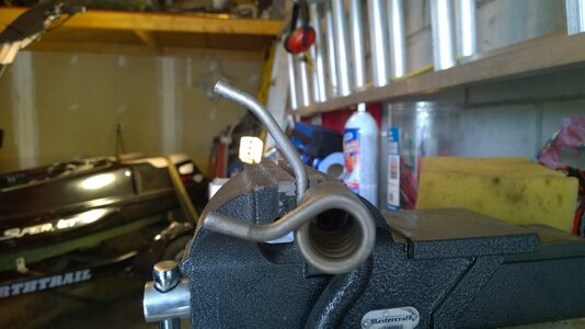
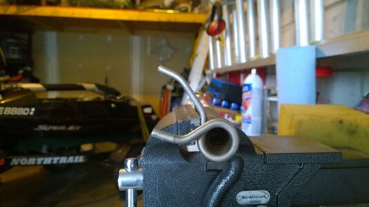
Last year around the last few weeks of the season I was getting all my gear together for a cold water, almost end of the year ride. It was the second weekend of October or so. As I was collecting my helmet, pfd, etc. etc., I heard a loud bang, it was really surprisingly loud. For a few minutes I had no idea what had just happened. I pulled my plugs and rolled the ski over, checked compression, I looked for a fuel system pressure buildup, I was fully expecting something to start burning that's how loud and sudden it sounded. Then I noticed a little round bar laying on the floor. I then realized, it was the pole spring. It blew up and left me with nothing for spring support. I recently priced out a new HD spring from Blowsion but between shipping and exchange it would have been about $100.00 by the time it arrived to my home in Canada. So I did the next best thing, I decided to try and figure out what I needed to do to turn my OEM round nose spring into a little more like an HD spring. Well, what I figured I needed to do to modify the OEM spring actually seems to have worked out rather well. I searched for quite a bit on re-bending the OEM round nose pole spring to get more tension out of it similar to a Blowsion HD spring but found nothing...seems typical for me. It never turns up when you want/need it but probably next week I will find a dozen threads or postings showing how people did this to their springs. But anyway, all I did was locked the long leg of the spring into my bench vice, put a pipe on it and just slowly and with minimal pressure, bent it forward by a good bit but a little at a time. I tested it multiple times to make sure the tension was getting better while not putting too much continuous stress on the spring. By the end of it, it would seem that I have a good OEM quality spring that has enough tension to make the pole nice and light, but no so much that the pole stands straight up on its own. My old Blowsion spring did that, it was nice in one way that when you remove the engine cover you didn't need a lock to keep the pole out of the way, but not so good for no handed jumps. On a few occassions the carbon chin pad almost made it into my helmet because of the old spring pushing the pole straight up once I let go. Here is the photo evidence of the new old spring configuration. It is currently not installed though as I am just waiting on replacement bushings. But it was installed with the old bushings in place and it really helped to ease the weight of the new pole. What also is nice about this mod, is not only is it free but so much easier to install than the Blowsion spring. I can install this in seconds with the pole and bracket on the ski. The Blowsion spring I found it easiest to remove the bracket and pole and install it with everything loose. It was usually about a 45 minute job by the time you remove everything to get to the bracket and then reinstall it all.
 

Attachments

  • WP_20170521_001.jpg
    WP_20170521_001.jpg
    89.9 KB · Views: 57
  • WP_20170521_002.jpg
    WP_20170521_002.jpg
    81.3 KB · Views: 58
  • WP_20170521_003.jpg
    WP_20170521_003.jpg
    87.5 KB · Views: 56
  • WP_20170521_004.jpg
    WP_20170521_004.jpg
    88.5 KB · Views: 55
  • WP_20170521_005.jpg
    WP_20170521_005.jpg
    78.5 KB · Views: 56
Top Bottom