Blaster 200 HP Carbon Fibre Blaster with 155mm Pump

Tyler Zane

Open Your Eyes
amazing build!

i have a new infatuation with blasters after just a few rides on a hardly modified one. i can only imagine the power and response you should expect. all thou video will not do it justice, i look forward to a little brappp footage.

your composite work looks next to none. that s2000 in your link is sick!

i have been running a oil filled pump for a while but the oil filled midshaft is brilliant, surf or flat.

Thanks for the positive feedback!
The website is under construction as we speak & will have pics of all of our new products. The S2000 on the website took 1 1/2 years of designing & has been completed for some time now. We are just completing our next design at the moment.
Oil filled bearings are great (as long as they don't leak) as the resistance is so much less, they run cooler & the bearing is always fully submerged in oil to protect it, which makes it last longer. Same deal with the seals.
Yeah, I know what you mean with the blasters, they feel like a GP bike on the flat water & a MX bike in the surf, closest thing to a bike I've ever ridden - it's a shame Yamaha stopped making them & went for the larger, easier to ride skis.
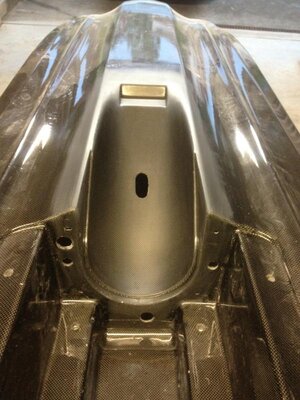
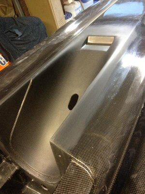
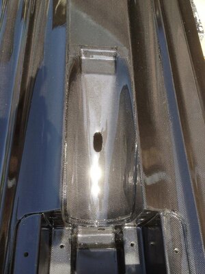
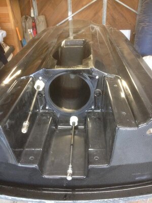
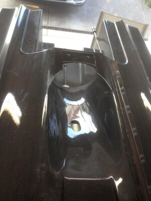
Here are some pics of the pump tunnel with the final sand before the clearcoat goes down.
The final pic is the tunnel once the clear has been sprayed.
We wanted to try to make this mod look as if the larger pump tunnel was moulded at the time the hull was made.
iphone pics 161.jpgiphone pics 162.jpgiphone pics 166.jpg
 
That looks fantastic. Your composite skills are amazing. Did I mention how I much I wish you guys weren't on the other side of the world? lol

SM
 
That looks fantastic. Your composite skills are amazing. Did I mention how I much I wish you guys weren't on the other side of the world? lol

SM
Thanks Scottie, your feedback is always well respected!
Yeah, we wish you guys were closer as well. Would be great to get feedback from you Blaster Boys after you have a few rides
 
iphone pics 189.jpgiphone pics 190.jpg
This is a 155mm pump shoe, it originally wouldn't fit into the pump tunnel, heights & other areas of the shoe were just not going to work.
We had to cut the shoe up & re-make half of it with epoxy to the shape we needed & tried to keep it looking close to oem. The plan was to have this modified shoe sand cast for future hulls as it is way too time consuming modifying an oem shoe.
We just sprayed some 2-pack epoxy black on to give an oem look.
 
031.jpgiphone pics 252.jpg
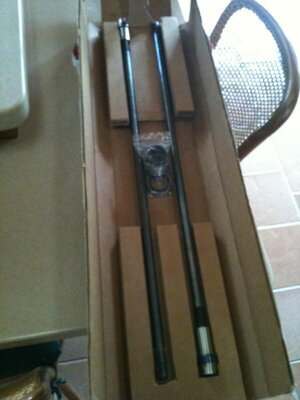
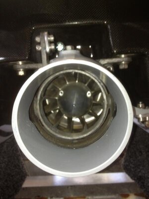
Skat-Trak made 2 custom prop shafts. The shafts are based on a setback pump style, plus an additional 100mm has been added to the length to allow for the 100mm that the pump sits further back in the hull.
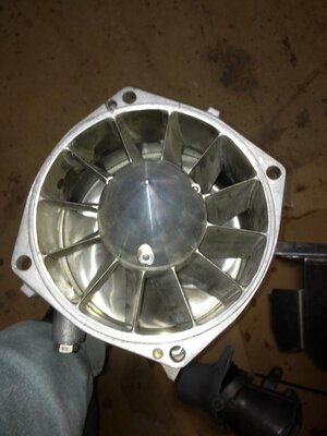
The pump was custom made by Skat-trak as a 12 vein stainless setback with 75mm hub.
A solid stainless impeller housing was supplied & both the impeller & pump housing were machined at the same time for perfect alignment, the big hub, thin blade swirl prop was matched to the liner
 
iphone pics 356.jpgiphone pics 357.jpgiphone pics 358.jpgiphone pics 359.jpg
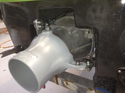
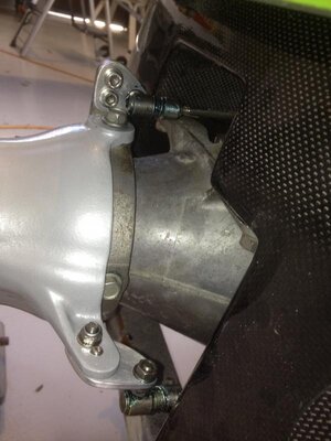
The 155mm complete pump is about 20mm longer than the 144/148mm pump, that meant that both the steering & trim cables were 20mm too short.
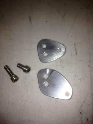
We could have made stainless adapters that screw onto the ends of each cable to give us the length (we still may do this), but we wanted to try these alloy brackets first.
We played with many different angles & shapes because as the steering nozzle turns, so does the angle of the cable & what was happening was the nozzle would turn more one way than the other due to the throw difference.
Once we found the shape that worked, we had the same amount of steering left to right.
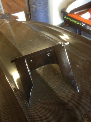
The first pic is of the 2 brackets we made.
The other pics are of the pump mounted in the hull with the new brackets & cables attatched.
Protek supplied us cast steering nozzle they suggested for the project.
 
451.jpgiphone pics 193.jpgiphone pics 212.jpgiphone pics 213.jpg
The first pic is of the aircraft alloy exhaust tube, it has a bonded carbon flange with stainless nuts that sit against the inside of the rear transom & a carbon flange that sits on the outside of the transom.
Stainless countersunk screws pull the 2 halves together & both carbon flanges are moulded to match the curve of the rear transom, not made flat on a piece of glass.
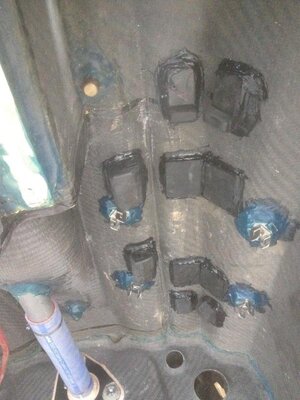
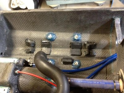
The other pics are of the rubber mounts to support the waterbox modified by Power Factor.
Alloy blocks are bonded to the hull with strap hooks screwed to them, these will hold the 2 rubber straps.
 
iphone pics 210.jpgiphone pics 214.jpgiphone pics 216.jpg
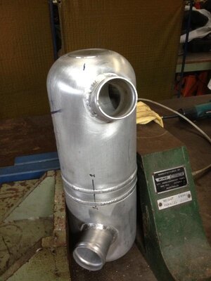
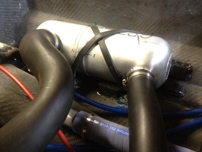
Here is the modified waterbox from Power Factor ready to be mounted.
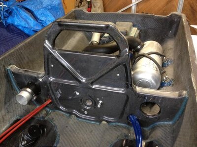
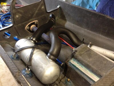
The 2nd & 3rd pic show the waterbox strapped in place & conected to the rear exhaust outlet.
On the 2nd pic you can see the bulkhead gives you options on which side you want to mount your piping for the exhaust, depending on which system your using.
 
iphone pics 217.jpgiphone pics 218.jpgiphone pics 219.jpg
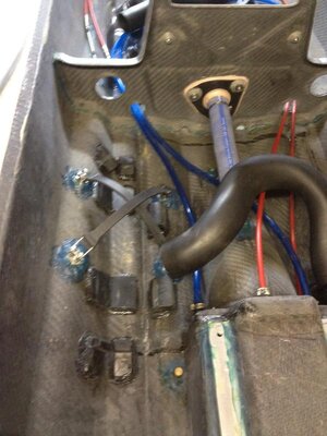
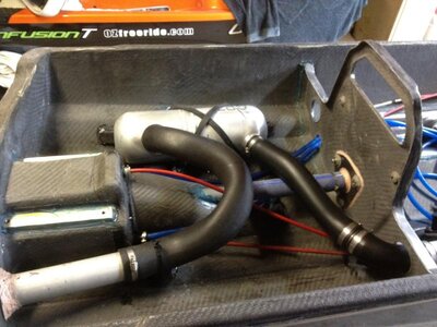
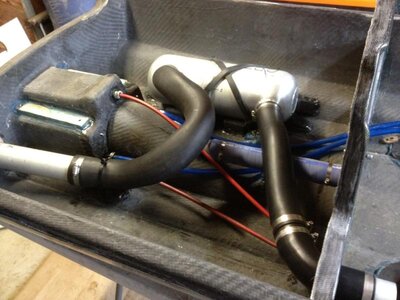
Here's some other pics of the what's happening behind the bulkhead.
All theexhaust hoses are made, connected, water lines are attatched, silicone hose is in place between the midshaft & pump tunnel & steering & trim cables fitted.
All hoses clear each other with none of them rubbing together.
 
Last edited:
iphone pics 230.jpgiphone pics 231.jpgiphone pics 255.jpgiphone pics 256.jpg
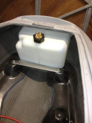
The Power Factor Pipe was the only way to get the full potential from the big Dasa motor, but that also meant the the pipe had to sit right where the oem fuel tank is mounted.
Most standup guys use a go kart tank that sits between the pipe & the flywheel cover which is normally 8 - 9 litres.
We wanted to use 2 fuel tanks on the blaster as it would be a pain in the arse to have to keep re-fueling every 15mins with just a go kart tank & wanted to achieve similar capacity as the oem tank.
We searched around for many different shaped tanks untill we finally found a tank that came close to fitting in the front of the hull.
The front tank would take much work to design a mount that would hold it on the right angle as to clear fuel pickups, top deck, etc. The other problem was designing a mount that would secure it firmly & still have the ability to remove the tank after the topdeck was bonded to the hull, many of the designs we came up with worked great, but didn't allow you clearance to remove the tank.
We kept the carbon fuel tank mounts that were to hold the oem blaster tank as we could see that we could use these 4 mount points for the front fuel tank bracket & as a mounting point for the Power Factor Pipe.
A small part of the carbon fuel tank front mounts were machined into to allow for the front fuel tank clearance & bracket removal.
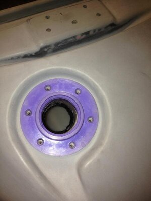
Another problem we had was filling the front tank, the only option to us was to use the oem external filler cap.
The first 2 pics show the mount in it's early stages, it was a couple of days of work of rejects just to get to this stage.
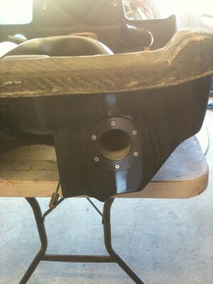
The pics of the tank shows the original filler cut off, a plastic plate welded in, then the filler re-positioned & welded as to match up with the oem filler cap in the topdeck.
A silicone hose is clamped between the tank & the oem filler cap neck in the topdeck.
 
Last edited:
iphone pics 257.jpgiphone pics 259.jpgiphone pics 260.jpgiphone pics 258.jpg
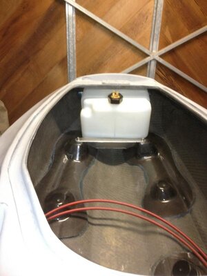
Here is the front fuel tank mount finished.
Thin rubber is bonded to the marine grade alloy plate for better grip, rubber is also place under the front of the alloy plate between hull surface & the the plate.
An alloy angle was cut to shape, heavily hole cut to lighten, rubber bonded to the face, drilled & tapped for straps & bonded to the front of the hull to secure the front of the tank.
The next 2 pics are of the tank in position, all that's needed is for the plate to be bolted in & the straps made to hold the tank securely.
The final pic is showing the plastic filler neck cut down & in place to line up with the filler on the tank. This plastic neck is just being used as a template to see how much we need to trim off so everything will line up correctly.
We are using a billet alloy neck, the hole hasn't been cut into the tank at this stage where the new position of the tank filler tube was welded.
 
iphone pics 233.jpgiphone pics 234.jpg
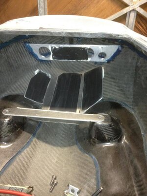
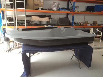
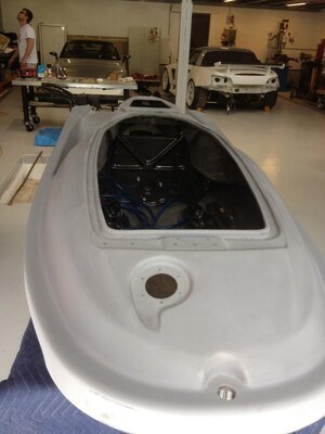
The hull is epoxy clearcoated & the topdeck is epoxy primed.
These pics are just after we bonded the topdeck to the hull & the glue has set, it's now officially a ski & not a whole heap of carbon parts lying around!
The next step is to get the hood together & spend some time in the spray booth
 
With the ingenuity, craftmanship, and design you all are showing why don't you just develop an electric hybrid engine that produces twice the horsepower for half the weight then you don't even have to worry about the gas tank. ;)
 
Top Bottom