Making of the SNX Hull

Vumad

Super Hero, with a cape!
Location
St. Pete, FL
Crunch Time! I am setting a goal date of April 19th. I want to have this ready for the Port Aransas ride. Put in 5 hours Wednesday, 5 Thursdays, 9 Saturday, and 14 Sunday. Still so much work left to do…

So this is about where we left off.

View attachment 271724

Pole area finished and first layer of body filler down for the hood opening.

View attachment 271725

Hours of sanding later and a high build primer. This part took longer than I had wanted. I raised the sides of the opening.
View attachment 271726
View attachment 271727

3/4" plywood will be used as the flange this time. Traced around the top deck and then measured 8" all around for the cut.

View attachment 271728

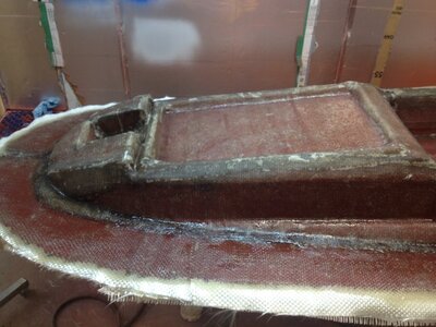
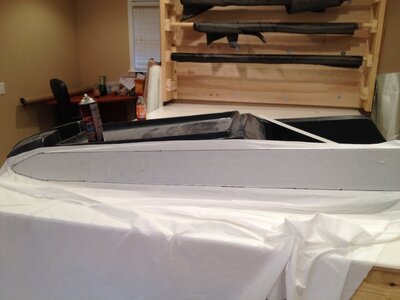
Used 2 part foam to adhere the top deck to the plywood. Masked off the finished rails with metallic tape so I could lay the body filler up against it. To seal up the rear, I used XPS cut into sections and wedged in at an angle. 2 part foam as an adhesive for the XPS and to "seal" the XPS so I could lay polyester body filler without it dissolving. Sanded down the XPS and layered body filler all around flange. Having a large compressor allowed me to use a DA sander which cut down the sanding time tremendously. Still, it was a tedious task.

View attachment 271729
View attachment 271730
View attachment 271731

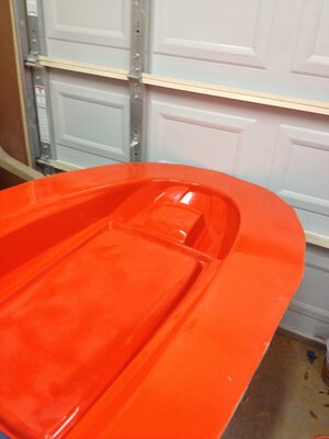
Several hours later it is ready for the surfacing primer. Almost...

View attachment 271732

I had a very basic design drawn up and some vinyl cut. Just like an imperfection on a plug will transfer to the mold, so will the raised the letters. The finished part will take on the decal if everything goes as planned.

View attachment 271733

Can you elaborate more on your work here? I just moved on from some half ass patch work to some quality mold making. However, my flanges recently have come out pretty poor (i've only made 3 small molds with flanges so far). I like the quality you have put down here. What kind of tape did you use to do this? I don't necessarily need pictures. Interested more in the steps you took to get a good connection to the flange without messing up the edge of the plug.

One of my problems is the parts I have made are much more complex than a flat bond rail. I've been using playing cards and packing tape to make a rail but it's time for a better finish. I think playing cards or construction paper is actually a good possibility on my complex shapes if I back it with foam or plaster. Any thoughts?

Going to start using duratech from here out. I've been using cheap lacquers which get an acceptable finish but my expectations are higher now.
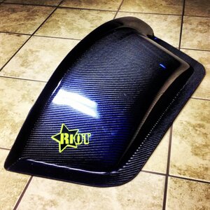
 
Carbon/glass fabric.

Can you elaborate more on your work here? I just moved on from some half ass patch work to some quality mold making. However, my flanges recently have come out pretty poor (i've only made 3 small molds with flanges so far). I like the quality you have put down here. What kind of tape did you use to do this? I don't necessarily need pictures. Interested more in the steps you took to get a good connection to the flange without messing up the edge of the plug.

One of my problems is the parts I have made are much more complex than a flat bond rail. I've been using playing cards and packing tape to make a rail but it's time for a better finish. I think playing cards or construction paper is actually a good possibility on my complex shapes if I back it with foam or plaster. Any thoughts?

Going to start using duratech from here out. I've been using cheap lacquers which get an acceptable finish but my expectations are higher now.

I use metallic HVAC tape anywhere I need to lay body filler up against to make a smooth transition from a finished to a non finished area. As long as you keep the layer of body filler that is on the tape to a minimum, it will peel off with a little effort.

As for what material to use for a flange, that depends a lot on the plug. Where at all possible, I prefer to use a solid material. I used playing cards on my first mold, but I wouldn't use them again. Depends if your flange is temporary or permanent as well. Also, whether I am going to use wax/PVA or a high slip semi perm would make a difference in how I create the flange.

I'll probably be using waxed poster board to flange the pole mold since the mold will be two parts.

Duratec is far better than a lacquer. Only issue I have with Duratec is that no matter what tip size and pressure I use, I always get orange peel. Not a little orange peel either. I have read that adding the high gloss to Duratec at a 1:4 ratio helps with the orange peel and also makes the final finish after wet sanding much higher quality. I have also seen 2K base/clears used to finish plugs. I haven't used either of these two methods yet, but will try one of them on the pole plug.

I have some pictures somewhere of a wing panel plug that was finished with Duratec/High gloss and wet sanded to 3000, the finish was mirror perfect. They pulled a mold off the finish with a semi perm, no PVA. Ideally I would like to get to this level. PVA glosses out and hides some flaws when sprayed just right. However in my experience there is a very fine line between perfectly sprayed PVA, and runny PVA. My top deck has 1 spot where the PVA had a small run (bottom of a rail). I debated on respraying the entire plug or just sanding out the small spot where the PVA ran after the mold is pulled. The rest of the application was flawless, so I'm going to finesse the mold finish on the small area where the PVA ran.


Sent from my iPhone using Tapatalk
 

tokarzl

itching my arms
a run on your plug will create a dip in your mold.... may have to sand transitions into it from all around it to minimize the dip

You can also cut duratec to thin it just ask your supplier for the thinner you can also get it through fiberglast but they are always expensive.

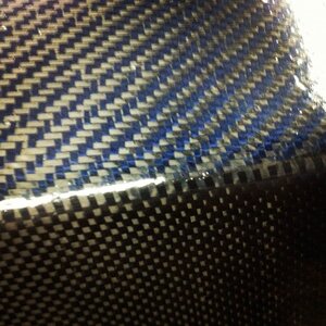
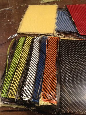
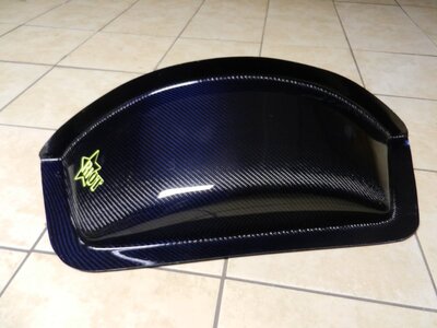
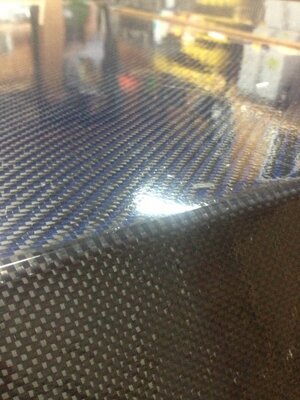
I have discussed the carbon with dyed fiberglass time and time again with John at Soller and I have preferred to use his carbon kevlar hybrid but I try to whenever possible lay carbon first around the outline so that the kevlar does not exceed past the trim line because the kevlar does not trim well and IMO allows a way for moisture to get into the laminate. My test panels with the dyed fiberglass have a lower surface quality and distorts the direction and spacing of the weave when pulling alot of vacuum. The carbon kevlar fabric lays like a normal 3k carbon and imo has a better finish with a weave that is "spread" if that makes any sense lol and really shows the 3d depth and beauty of the weave. The pictures help show it the various color one is test panels of sollers colored fiberglass carbon material
the wheel tub is the blue carbon kevlar from soller and the other part is a mod dirt roof that is edged with a PW 3k carbonphoto1.jpg photo2.jpg photo3.jpg photo4.jpg DSCN1449.JPG
 
It is a very small run, but it will probably take a bit of sanding to minimize it. It's at the very bottom edge of the rail. We will see how it comes out.

I see what you are talking about with the colored glass hybrid. The tows hold together and don't want to spread out to make a nice "fill". That wheel tub is beautiful.
 
New direction for the project…

View attachment 272663


bryan_cranston_may_be_another_year_older_but_hes_still_just_as_awesome_20_photos_video17_1425749921_zps809ace9f.jpg
 
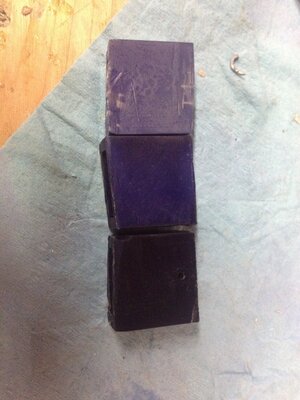
Good eye. Yes. The sodium hydroxide, sulfuric acid, and DC power supply gives it away. No blue crystal meth for me, just blue aluminum.

First test samples came out of the dye today. I still need to seal them this evening. I was up until 4am last night tweaking the setup to get the oxide layer thick enough. At first I wasn't building much of any oxide layer. My acid/water ratio was off. Added more acid and re etched. After that they built up a nice thick layer and took the dye very well. The parts are a very deep blue.

We'll call this a proof of concept / color test. I didn't take any measurements to determine what my oxide layer is, or what the current draw over time was, or do any current density calculations for the work pieces. I just wanted to make sure that I have the process down and can get a satisfactory result. From here I can progress to hitting a certain oxide layer thickness and then doing my motor mount inserts, cooling lines, and exhaust tube. I'll do a right up on it tonight or tomorrow.


Sent from my iPhone using Tapatalk
 
Last edited:
Getting started anodizing…

I wanted to learn something new, so rather than paying someone else a couple hundred to anodize some parts, I decided to take it on myself. Heres what I bought:

4 stainless steel pots - $32
30a 12v DC power supply - $25
Sulfuric Acid 5 gallon (battery acid) - $26
Hot Plates - $30 (had this already)
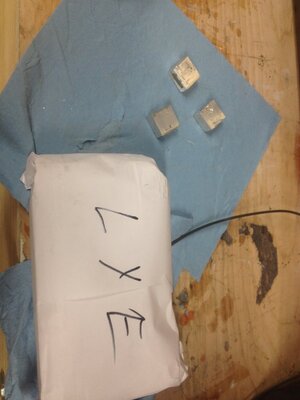
Sodium Hydroxide (Lye) - $15
Rit Blue Dye - $10
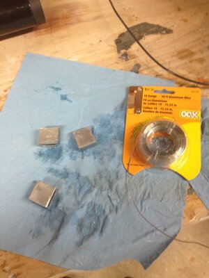
Aluminum Wire - $7
4"x24" 0.25" 6063 T5 Alu - $35
Rubber Maid 10 gallon tub - $10
Rubber gloves - $5
Misc. Electrical Wires & plug - $15
10 Gallons distilled water - $9

Total ~ $219

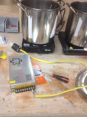
First had to wire up the DC power supply

image-13.jpeg

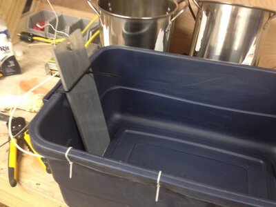
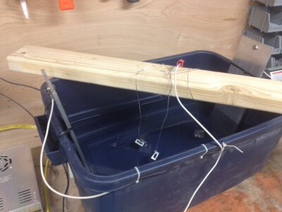
Next I cut the 24"x4" .25 aluminum plate in half. Drilled a 1/4" hole at the top of each piece and connected the two pieces together with a 12 gauge copper wire (from some romex I had left over). The connections were made with a 1/4" stainless bolt and ring connectors crimped to the wire. Another 12 gauge wire is connected to one side and then to the negative post on the power supply. Zip ties hold them in place. The plates will serve as my cathodes.

image-16.jpeg

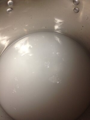
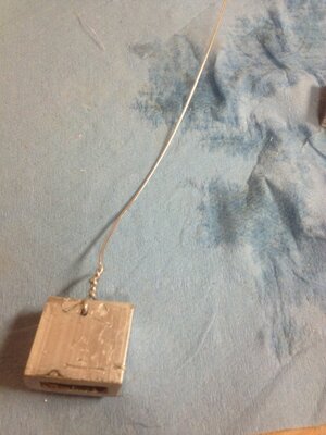
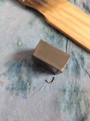
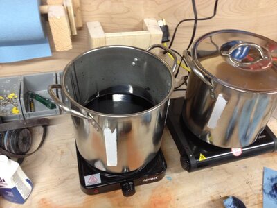
Some 1"x0.5" 6061 rectangular tubing was cut up into 1" sections for testing. In one of the pots a half gallon of distilled water was mixed with several tablespoons of sodium hydroxide (4 maybe). The test pieces were added to the pot to etch them for 5 minutes.

image-20.jpeg
image-12.jpeg

While the test samples were etching, I added 2 gallons of distilled water and about a half gallon of sulfuric acid to rubbermaid tub. Holes were drilled in the test samples and bare aluminum wired was used to connect and suspend them in the acid bath.

image-15.jpeg
image-11.jpeg

The three pieces were connected together and then to a 12 gauge wire running to the positive post on the power supply. A scrap piece of 2x4 was used to suspend the pieces in the acid bath.

image-14.jpeg

Power turned on and a circuit was verified. Almost immediately the cathode plates will start to form tiny bubbles. The first run was for 1 hour. I didn't see much of an oxide layer, so I added another gallon of sulfuric acid. This time the cathodes were producing quite a bit more bubbles. I let this run over night (about 3 hours). In the morning I removed the test samples and a very obvious oxide layer had formed.

image-17.jpeg

One sample was placed in Rit Navy Blue dye and another was placed in the Rit Royal Blue dye. Both pots were made with half a gallon of distilled water and 4 tablespoons of dye. The dye was heated up to 150 degrees and the samples left in for 30 minutes.

image-18.jpeg

The parts came out very dark. The third piece was placed in the royal blue dye diluted with another half gallon of water. This time I left the sample in for only 15 minutes. After this all of the pieces were placed in boiling water for 30 minutes.

test sample.jpeg

Top to bottom: Royal blue (15 minute), Royal Blue, Navy Blue. The parts took the dye very well. I didn't clean up and polish the test parts prior, so the finish doesn't look fantastic. But overall not bad for an initial attempt. I ordered some Nickel Acetate for the sealing process, an analog amp meter, and some anodizing dye. I'll run a larger test that is polished with the nickel acetate and new dye when I get it in. If that goes well I will run the motor mounts, cooling, and exhaust tube.

Last layers of reinforcement was added to the mold today. I'll have that pulled tomorrow and hopefully a top deck infusing by Tuesday.
 
Last edited:
Top deck only partially laid up. Some things took longer than expected (as expected). Here's some pictures of what was done the past few days…

First layer of reinforcement after the skin coat set.
image-19.jpeg

Completed reinforcements. Lay up schedule:
8oz twill (skin)
18oz Roving
1.5oz Mat
18oz Roving
1.5oz Mat
37oz Roving / stitched mat

I found a local supplier for glass and polyester resins. Their pricing structure is a little different than US Composites. I ran out of roving half way through cutting the mats. They wanted almost $10 a yard for 20oz roving… Yikes! However they had this ridiculously thick roving/stitched mat used mainly in boat construction (So I assume) for only $3 a yard. Imagine 1708 and woven roving stitched together. Insanely thick stuff. I could use it for a comforter...

Anyway, I learned a lot from the last two molds I made. Things only experience can teach, like how much you can make a certain fabric conform and how to cut the fabric, but mainly I learned patience. I spent around 12 hours laying this one up. A lot of attention was placed on removing as many bubbles as possible. The last layer has a few bubbles, mostly under the 8oz tape I used to seam the different sections of roving/mat, but at that point it is just there to add stiffness anyway. The skin layer was nearly perfect and the next 4 layers were excellent.
image-20.jpeg

This mold was by far the most difficult to remove. The entire flange ripped off the plug and the rails were damaged in the process of prying it out. The surface looked really good, with exception to the areas that will be turfed/trimmed. I didn't spent a lot of time prepping the trey since it will be turfed, or the hood opening as it will be trimmed out.

image-21.jpeg

While the IMC was setting, patterns were made.

image-25.jpeg

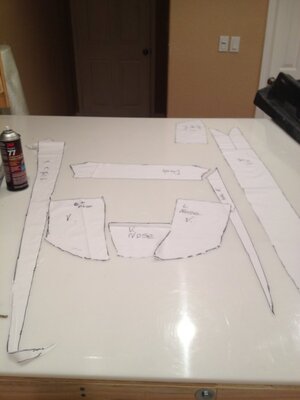
Here are the patterns for the visual fabric layup.

image-24.jpeg

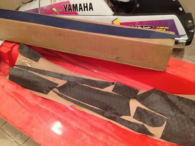
Honeycomb, Blue Hybrid, and 4x4 twill all cut.

image-29.jpeg

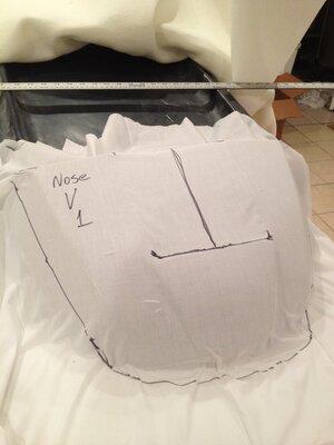
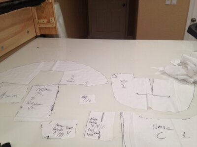
Due to the nose directly handling the stress of the pole, a lot of thought was placed into the layup schedule in this area. I'll go into more detail when I finish laying it up, but it is tentatively 150oz, 6mm Soric, and 0.41" thick at the mounting point. It transitions out to 58oz, 3mm core, and 0.185" thick at the sides of the top deck. Due to the progressive thinning of the layup, 3 different template sets were made for just the nose area.

image-26.jpeg

image-27.jpeg
 
Last edited:
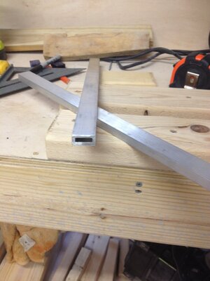
While the IMC was curing, I tackled a project that I have been concerned about for awhile. For the adjustable footholds, I will need a rail that will fit a carriage bolt perfectly. Unfortunately, I was unable to locate exactly what I wanted. Looks like I left with fabricating it. Since I don't have a mill, and my metal working skills are sub par, I was going to have a machine shop do the job for me. However I ran into the same issue I had the last time, job is too small. So I took it upon myself to figure it out.

First I bought several different size carriage bolts and put the caliper to them. I wrote down the head height, head width, and the square height. Next I checked what size extruded aluminum square/rectangle tubing was available. I settled on using a 5/16th carriage bolt and 1" x 1/2" x 1/8" 6061 rectangular tubing.

image-31.jpeg

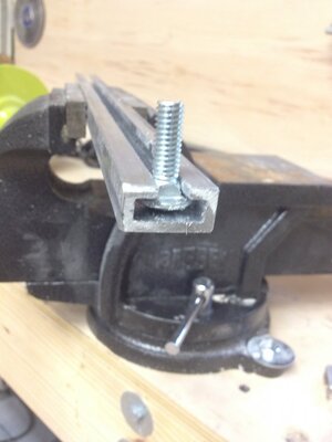
The plan is for the head of the bolt to slide in the channel while the square portion slides through another channel milled into the side. The idea is that the head of the carriage bolt will have enough room to slide back and forth, but not enough to allow the square portion of the bolt to fall out of the milled channel. This, along with a cam locking nut, will allow the footholds to be easily moved and removed without the use of any tools.

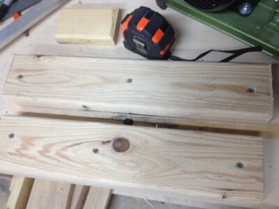
My options (that I could think of) were to buy a mini mill and learn to use it (something I always wanted to do), cut it by hand with a hack saw (no thank you), or rig up some sort of jib with a router. Router jig seemed the easiest. I bought a small trim router from harbor freight and a 5/16" straight slot wood bit. After doing some research, I found the correct bit to use for this is an O flute (any machinist feel free to correct me if I'm wrong). Sadly home depot does not sell these. Wood bit it is. Mounted the router underneath my bench and used the scrap pieces of anodized aluminum to line up two 2x4s to act as a guide.

image-34.jpeg

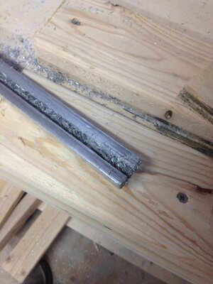
Sprayed the aluminum down with some cutting oil and fed it through. It took a couple of minutes for each piece and made some horrible sounds, but it cut a straight line through the center.

image-35.jpeg

Here is the bolt sitting in the channel. The aluminum will be anodized and infused into the foothold wells. The stainless cam lock nuts should be here this week. More of that when I get around to creating the foot hold wells.

image-36.jpeg

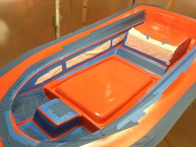
Mold taped off.

image-30.jpeg

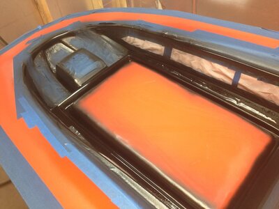
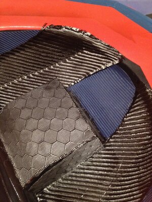
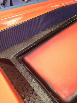
With this layup I am using several different visual carbons. Where each of them meet I am laying out a black "seam". It worked well to hide the transitions where the pump tunnel is on the bottom deck. Hopefully it works on the top deck as well.

image-33.jpeg

Visual carbon laid up. That's as far as I can get tonight. Tomorrow night I am hoping I can lay up the structural carbon and infuse the deck.

image-38.jpeg image-37.jpeg image-39.jpeg image-40.jpeg
 
Top Bottom