1995 Yamaha Superjet Resto-Mod

After trying to install the pump yesterday and running into a few issues, I’m having some trouble with my steering cable binding. It’s binding pretty badly and after spending over $2500 on a mag pump, the last thing I want to do is take an angle grinder to it... any ideas? 65A7495F-7C65-4954-B7E3-8AC908734774.jpeg709B3457-AD81-4B2F-90AE-52EDDA565B4B.jpegEB29AD0E-D91A-4B11-9C0F-9C3A8763E709.jpegE5C5E1BE-9649-45B9-B578-F5144CA9CA42.jpeg
 

hornedogg79

dodgin' bass boats
Flip the stator section. You have to pull the alignment pins. Use a straight edge on the mounting feet to align the wear ring and reduction nozzle when you put it back together.

Sent from my Moto G (5) Plus using Tapatalk
 
Duhhhh I didn’t even think of that... I have to remove the pump again today anyways so I’ll try that first and see if it makes a difference

It's hard to tell from the angle of the pictures but is the steering cable straight back from where it mounts to the hull to where it mounts to the steering nozzle, or angled upward?

The old style square nose steering nozzle has the little arm very low on the nozzle, and the little ball thing is mounted so the joint is above the arm. Newer 08+ nozzles have the steering arm more in the center of the nozzle, and the ball i smounted to point downward. Looks like you have a newer style nozzle with the arm more in the middle, with the ball mounted upward, which would cause an upward angle of the steering cable from hull mount to nozzle. So you'd want to do the flip thing.

But I can't tell from the angle of the pic.

I did flip the ball and it solved the problem. I’m running a Pro-Tec steering nozzle and I was filling the service manual instructions, which is backwards from that nozzle. I am using the correct Pro-Tec adapter for using it without a trim system.
 
So, I’m feeling the burn on this build. This is my first ski and I thought is was gonna be a breeze. HA! Reality check. Using the stock alignment pins for the pump, I managed to almost completely pull the threads out of half the front pump inserts. I removed my pump, cleaned everything out thoroughly, and checked the threads. They will hold torque up to 18 foot pounds but I decided not to push it. Spec is 24 foot pounds and the rear 2 are fine and will hold 24. Honestly it was those damn alignment pins. I eventually took them out making my life much easier. However the damage was done. I had my pump aligned almost perfectly using the Cold Fusion alignment tool, but I had some side to side clearance issues. I took a dremel and opened up the holes for the mounting a bit and it seemed to help but it’s had to try and align the pump and tighten the bolts by yourself. Plus flipping the ski trying to check alignment all without scratching my fancy new paint job ha. I just want to ride!
89D6B20F-8D57-410F-9C53-01D20E4CEF9B.jpegB45B81C6-9790-44FF-ADB7-2D19857BB3FA.jpegBAA91885-484D-41D6-9A31-3765EA4F1E93.jpeg777B1953-2381-4FB3-B38E-FC582FC06142.jpeg21101399-27AF-4E91-8977-AA7F461E02DB.jpegB61946DA-ECB3-4979-AC1F-E58830A96AE3.jpeg
 
I haven’t come to a conclusion yet about the pump driveshaft being bent. Some say to run it, others warn not to do it.

While I’m making a decision, I decided to go ahead and build up my e-box and wrap some wires. Still waiting on my Purple heat shrink to arrive for the rest. But it’s looking pretty tidy! I filled all of the connections with dielectric grease, and even disassembled my new starter switch in order to apply dielectric grease onto the contacts. No use waiting until they’re already corroding right?

118CE73D-BE29-4081-8AD9-A3821F0DDBCF.jpeg0EB23754-6935-426E-A68F-21C42EA3430B.jpeg
F6A9A5E2-8507-4E48-BD05-31F007B6D844.jpeg
92767C75-A3EE-4A5C-8513-B14EEA3D33F7.jpeg
9D1398AE-29B8-4AED-BC4F-18EF8F4CE51B.jpeg80FBFEA8-0644-4597-8800-DBED6DBA0FBD.jpegE55814D9-D969-45E7-AF46-6F0C7E315ECC.jpeg6A691C8A-4426-41B5-BDC1-701AE5FA1350.jpeg0D9E2FAB-AA29-4C1C-B3FA-ABD5BEE48A19.jpeg1ACF9E4D-4F1E-40A5-BC4B-11C92190BFB9.jpeg
 
Last edited:
I’m gonna plea temporary insanity, if you look at anything for too long, you’ll lose your mind haha. I got my pump all aligned with the wobble on center. It took a little grinding from the mounting holes to get it strait but I got it. I realize now that the tool for alignment is important to show you where the center of your midshaft will fall, After removing the tool I realized that my shaft wasn’t center with the tunnel and had a real duhhh moment! The tunnel has no relevance of “center” for the shaft. That’s what the tool is for. Ding dong.

With all that out of the way I’ve been making some progress. Thanks to @JetManiac for saving my a$$ and pointing out that I had assembled my midshaft/seals incorrectly. I had extra seals and got that sorted, so now I’m pressing the shaft back into the housing. Before I did, @Harbor mentioned a way to check my spline engagement. Since I had the shaft out I figured I would see how deep the shaft can go before bottoming out, marked it and measured it. I came up with about 31.5mm from the end of the shaft to bottom out. I understand that it is necessary to give at least 5mm clearance before bottoming out, with that said the stock spec for the shaft is 19.5mm exposed from the back of the housing. Should I adjust my depth accordingly for this shaft or run the stock 19.5mm? I have heard the midshaft splines aren’t as long as the shaft itself, so this might be unnecessary. What do you think?

52219170-612F-435D-88D9-D2B44F2542AA.jpeg68398877-1112-41BD-BA32-99B5B962610C.jpegF564C796-805D-469E-84EB-497E98AF7166.jpeg
 

JetManiac

Stoked
Site Supporter
Vendor Account
Location
orlando
Assemble midshaft with shaft press through at 20mm to start. Stock spec is 19.5-20.5mm.

Then put some grease on driveshaft splines, but only on the front 1/2 inside the splines only.

Then bolt up the midshaft. Remove it and see where the grease spread to, which shows the exact overlap if done correctly. If not clear, remove midshaft, remove grease from splines. Retry. Underlap of approx 3/16" is a good goal, which is more engagment than on a stock SJ. You can then press midshaft less or more as needed, but be careful not to over press midshaft and destroy the bearing.

If shaft is pressed much deeper than stock, we add an extra coupler thrust washer to restore coupler to stock location.
 
Ohhhh didn’t even think about coupler engagement! Great advice, thank you. Also by under lap you mean the amount the grease didn’t reach towards the back?
Assemble midshaft with shaft press through at 20mm to start. Stock spec is 19.5-20.5mm.

Then put some grease on driveshaft splines, but only on the front 1/2 inside the splines only.

Then bolt up the midshaft. Remove it and see where the grease spread to, which shows the exact overlap if done correctly. If not clear, remove midshaft, remove grease from splines. Retry. Underlap of approx 3/16" is a good goal, which is more engagment than on a stock SJ. You can then press midshaft less or more as needed, but be careful not to over press midshaft and destroy the bearing.

If shaft is pressed much deeper than stock, we add an extra coupler thrust washer to restore coupler to stock location.
 
Since I am running the Cold Fusion tank, I decided to make myself some block off plates for the old gas fill hole. I decided not to close it up with fiberglass in case I ever wanted to use a stock tank. I made 2 plates out of aluminum and 2 stock filler neck gaskets. 1 for the inside and 1 for the outside. Put a lil silicone on them and bolted it in. A4DC8B9E-BF20-4DCE-B574-0B278556D263.jpeg388EF5E7-29A7-46CA-B6CF-C29A4B69A163.jpeg

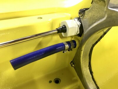
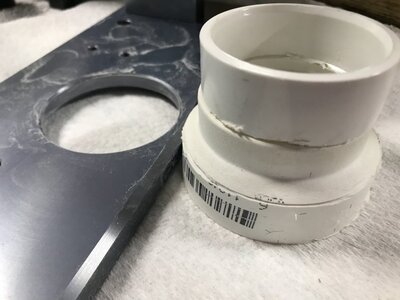
Next up is my handlepole mount... turns out it is missing the collar for holding the cable guide. This turned out to be a good thing because I was able to find a 1.5” to 2” plumbing fitting that would accept the stock cable guide. With some dremel cuts and sanding I was able to make a really nice fitting piece. The fitting had a lip inside from where it is formed together, it created a perfect surface for the groove on the stock cable guide and is really a tight fit... I was impressed with how this came out!!
815E6640-06C4-458F-BA7C-174CB2DCF950.jpeg
2E7D564E-1F95-4CD9-A1BE-94F0012457FF.jpeg
03278884-150F-4FEA-ACCE-E761B71FBCF3.jpeg
BAA3F023-F85D-4B10-AA3D-BD2FBD781089.jpeg
1C488C6E-9858-49C0-B2A4-E06A2EB1F7C5.jpeg
8BC70620-8B17-4D5C-B0B4-EB6C8EB2EB31.jpeg
1DBD0544-A3E2-4221-9F2A-DE6AF780C1C8.jpeg
86FD12BA-D791-466A-91C8-8CF0FBA56A1F.jpeg
 
Top Bottom