B-pipe cooling, routing water lines

F

Freestyleriverrat

Guest
SuperJETT said:
One thing I noticed about Jetworks' reply, they mention "best rpm". I could care less about rpms.

Yeah I noticed that as well. I know how I am going to run my cooling now and I will just go from there on dialing it in. I think that is the main thing, just knowing how your particular setup works and what option you have while tuning. Like freestylegeek was saying he tried out a couple of different setups for his application and finally selected the one that worked best for his riding style.

I think this thread gives a nice overview of the different set ups as well as pros and con of each. They all work well to cool the motor it is just a personal preference on how you want it done.
 
F

Freestyleriverrat

Guest
michael950 said:
On a side note, FP EXPLICITLY states to have the 90 off the Tee go to the stinger and the in line of Tee to the bypass.

I guess its a personal preference.

Just run a y-fitting and be done with it :biggrin:
 

crammit442

makin' legs
Location
here
The REAL bottom line is that whoever designed and ported your motor should be able to get you the water routing that best compliments the motor you're building. Different shops prefer different routing for different reasons. Not very many riders have the time or inclination to test every possible combination. That's why once you decide on a shop to do your work you should listen carefully to their recommendations for cooling, prop, jetting, etc.. Most shops design their motor packages based on the COMPLETE package. If you don't run what they want you to, you may be missing out on the performance they designed into the package. My Jetworks stroker is put together EXACTLY the way Art wanted it. He's done the homework and that's why he gets paid the big bucks.:wink:

Charles
 

SuperJETT

So long and thanks for all the fish
Location
none
hangtime said:
So the waterbox doesn't fill up with water too much and it would make the pipe perform better .I dont honey know man :banghead:

What I'm getting at is giving a reason like "because so and so said to" doesn't hold up very well, it's better to get to know the real reasons behind stuff. The tee'd leg will have less pressure, therefore less water. If you were using a Y, then both legs would see equal pressure and it wouldn't matter.
 

#ZERO

Beach Bum
Location
Florida - U.S.A.
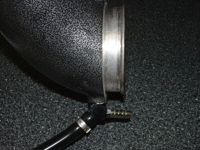
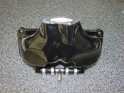
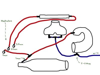
Here are some pictures of my cooling system on a Yamaha Superjet. I ran a single line from the pump to the head pipe with a custom made stainless Y-fitting at the bottom. The other part of the Y-fitting attaches to a stainless steel T-fitting at the bottom of my exhaust manifold. The line at the top head pipe attaches to a stainless steel T-fitting straight to the stinger tip with a 1-mm restrictor (hole) and the other to a water outlet. I tapped the inlet of the stinger to accept a Weber DG 32/36 or Holly 5200 series carburetor air corrector jet for easy adjustment with a screw driver to change the flow to the water-box. Riva also makes an exhaust water filter restrictor that accepts Mikuni main jets. I am using a Riva Girdle Head with dual cooling going to individual water outlets. Each of the head water outlets has a 3.5-mm restrictor (hole) and the stinger bypass has a 2-mm restrictor. This makes for easy water temperature adjustments by changing restrictor sizes. My local hardware store had the 3/8†nylon dowels in half inch length with various hole sizes. I run in 65 to 88 degree water and the temperatures out of the head are about 117-128 degrees with only one supply line.
 

Attachments

  • Y-Fitting.jpg
    Y-Fitting.jpg
    101.1 KB · Views: 716
  • Exhaust T-Fitting.jpg
    Exhaust T-Fitting.jpg
    174.4 KB · Views: 926
  • B-Pipe Water Diagram.jpg
    B-Pipe Water Diagram.jpg
    27.3 KB · Views: 1,181
F

Freestyleriverrat

Guest
Single line = 6-7.75mm id (mine measures 7.75mm id)

Restrictors (mm) for #.0

3.5 (2) + 2 + 1 = 10mm of flow + psi loss through pinn holes in head pipe

10mm > 7.75mm supply -> lower system psi
**10mm can flow 129% what a 7.75mm line can supply

FP system reccomendations a 4mm res on bypass w/ single line system

4mm + whatever stinger is 6mm(**)? > 7.75mm -> flow on exhaust side of system
**= 10mm, so a restrictor on the stinger might help keep a little pressure in the system to operate the water injectors in the head pipe. A simple 3mm restrictor after the FCV on the stinger plus the 4mm pisser would flow 90.3% what a a 7.75mm line can supply. 51.6% of that is bypasses through the pisser while the other 38.7% can go to the stinger. Leaving 9.7% for injector function.

For the dual circuit cylinder side line (7.75mm) a 6mm pisser can flow 77.4% what that line can supply.

#.0 Water goes the path of least resistance so more should flow to the cylinder side of your set up, which is fine.........you don't want the exhaust too cool. From the temps you listed sounds like yours is working just fine.

**I think all setups work it is just a matter of tuning them according to system setup/psi. I think I am looking at things way to analytically now :banghead: I apologize :smile: I'm pulling the fugures out of my arse.....but they are based only on diameter of the lines and restrictor size.
 
Last edited by a moderator:

ski4

gonzo
Location
cleveland
holy jesus this has become to confusing for me to even come close to grasping.
now i wish i just had single cooling line on mine and didn't get my head all polluted with this mess
 

hangtime

Speak up ,don't kiss azz
Its making it real hard to figure out with all the different choices .:frown:

I don't have a mechanic to figure it out for me but most of the time I ride in water that is between 35(winter ocean) to 65 (summer ocean ) but occasionally ride at my dad's lake in the summer and the water gets to 80 or so .WTF am I gonna do :banghead: :banghead: :banghead: :banghead: :frown: :frown: :frown:
 
F

Freestyleriverrat

Guest
Here are more #'s out of my arse :biggrin: This just helps me make my decisions, but I have not tested anything yet so my though process maybe off. Make of it what you will.

% that can flow through restrictor supplied by a 7.75mm line

1mm = 12.9%
2mm = 25.8%
3mm = 38.7%
4mm = 51.6%
5mm = 64.5%
6mm = 77.4%
7mm = 90.3%
8mm = 103%
 

SuperJETT

So long and thanks for all the fish
Location
none
Are you doing actual flow numbers for a given tube size or just comparing area or diameter?

10mm has 166% the cross sectional area that 7.75mm does. Calculating actual flow is possible, I just don't have the formulas handy.

Freestyleriverrat said:
Here are more #'s out of my arse :biggrin: This just helps me make my decisions, but I have not tested anything yet so my though process maybe off. Make of it what you will.

% that can flow through restrictor supplied by a 7.75mm line

1mm = 12.9%
2mm = 25.8%
3mm = 38.7%
4mm = 51.6%
5mm = 64.5%
6mm = 77.4%
7mm = 90.3%
8mm = 103%
 
F

Freestyleriverrat

Guest
I'm just dividing the ID size of the restrictor(s) by the ID of the supply line just as a reference to follow.........you can see what I am shooting for :biggrin: %'s are just a general comparison that should correlate to the achual flow rates. I'll look around to see if I can find a formula..........
 
Last edited by a moderator:
F

Freestyleriverrat

Guest
I suck at math but I would imagine you would need the operating pressure (which quickly fluxuates) to accratly calculate the flow rate.......plus when the flow control valve opens will affect it as well. I just wanted to emphasize that when your restrictors flow more than the line can supply you have almost no system pressure which effects how well the water injection works, especially at low rpms. If you had a flow control valve mounted anywhere on the system it also may not function properly b/c you would not have enough pressure built up to open it.
 
Last edited by a moderator:

Frosty

New York Crew
Location
Western New York
OK... so I am currently running pretty much the same set up as Jett and using 3 pissers, all 6MM and things seam fine. I have been running this set up for a few years now.

However, with 3 6mm pissers do you think I am not building enough pressure in either curciut? Should I change one or all to 4mm?
 

Attachments

  • b-pipe_blank-jpeg.JPG
    b-pipe_blank-jpeg.JPG
    3 KB · Views: 1,314
F

Freestyleriverrat

Guest
I don't want to dish out wrong advice I am just trying to explain how am thinking of this whole cooling situation. BTW did I mention I suck at math :biggrin:

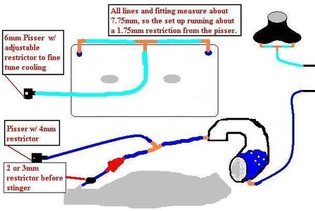
For dual circuit cooling this is the how and why I am going to run mine right out of the gate.

Cylinder side

One line (7.75mm) split into two going into the manifold and through the cylinder. Rejoined via a T-fitting to exit a single 6mm pisser to keep the flow across the cylinder close to the same for more uniform cooling.

6/7.75= 77.4% of that water activly flow through the circuit. If that proves to be to much cooling I can run a 5mm restrictor and run roughly only 64.5% through that circuit.

Exhaust Side

One line (7.75mm) going into the bottom of the head pipe, out the top into a t-fitting where it is diverted to a 4mm pisser and FCV. Between the FCV and the stinger I want to mount a 3mm restrictor.

Why to mount the 3mm restrictor? When the FCV opens the pressure in the system should drop to almost nothing b/c the FCV can flow 100% what that 7.75mm line can supply b/c the ID of the FCV was 7.80mm w/ my vernier caliper. Add to that the split going to the 4mm pisser and the system can now flow 152% what that line can supply = free flow w/ little to no pressure.
By mounting the 3mm restrictor you can still keep pressure in the head pipe when that valve opens.

4mm pisser + 3mm restrictor = 7mm
7mm total restriction/ 7.75mm supply = 90.3% flow

100% - 90.3% = 9.7% -> pressure in the system to operate water injection

In addition 3mm restrictor should flow 38.7% of that through the stinger and the 4mm bypass should flow 51.6% of the total.

38.7% + 51.6% = 90.3% flow through restricted pathways

90.3% + 9.7% = total system flow (at any constant pressure)

Below is a pic of how I think it should look based upon the information I used to draft it up taking into account estimated flows, compiled technical reccomendations and goals of even cooling of cylinders and indipendent circuit adjustments.

**Keep in mind that by keeping pressure in the exhaust side it should allow for more accurate turning of the head pipe.......which was the whole reason for its design.....

I could be wrong, but I am willing to at least give it a shot b/c pretty much every set up I could think of has been done and works to cool the motor.....I think it is just a matter of degree of efficiency.
 

Attachments

  • coolingsetup2.JPG
    coolingsetup2.JPG
    40 KB · Views: 695
Last edited by a moderator:

Frosty

New York Crew
Location
Western New York
Thanks for the info...

I guess my question is more... how important is curcuit pressure or water flow... I mean, if you are flowing more water through the curcuit then shouldn't that cool the system more effectively? And, in terms of the head pipe, you can only push so much water through the adjustment screws no matter how much pressure you have right?
 
F

Freestyleriverrat

Guest
TXJFrosty said:
Thanks for the info...

I guess my question is more... how important is curcuit pressure or water flow... I mean, if you are flowing more water through the curcuit then shouldn't that cool the system more effectively? And, in terms of the head pipe, you can only push so much water through the adjustment screws no matter how much pressure you have right?

Yeah it does not take allot of pressure to run them but by keeping a little pressure in there the system should be more responsive to pressure changes ie.: rpms. Any more restriction and you will be cutting down on the cooling of the pipe, the less restriction and you will increase the cooling of the circuit. The more water flow through a curcuit the more cooling you get.

This is just my take on things, but it makes sense to me so that is what I am going to toy with :fingersx: If nothing else it is a starting point for me.
 

Frosty

New York Crew
Location
Western New York
Freestyleriverrat said:
Yeah it does not take allot of pressure to run them but by keeping a little pressure in there the system should be more responsive to pressure changes ie.: rpms. Any more restriction and you will be cutting down on the cooling of the pipe, the less restriction and you will increase the cooling of the circuit. The more water flow through a curcuit the more cooling you get.

This is just my take on things, but it makes sense to me so that is what I am going to toy with :fingersx: If nothing else it is a starting point for me.

Thanks for that... that helps me allot. So, by that rationale, with my set up I am running a very cool system :cool2:... however, does that mean I am also sacrificing some performance by running too cool?
 
Top Bottom