You are using an out of date browser. It may not display this or other websites correctly.
You should upgrade or use an alternative browser.
You should upgrade or use an alternative browser.
DIY Total loss or MSD TL upgrade box 270USD?
- Thread starter Christian_83
- Start date
- Location
- Riverside, CA
The difference between your method and the pdf document is that you
measured the difference of the pick-up coil, located in relation to tdc. If the
reluctor begins at 47 deg btdc, your measurement would be correct.
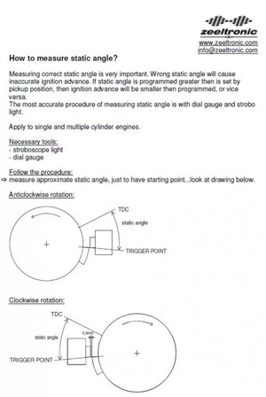
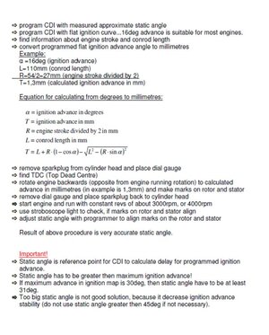
The pdf is instructing us to measure where the reluctor begins in relation to the
pick-up coil and tdc. Both my measurements of the stock reluctor position
and the specs provided by Wax indicate that at 47 deg btdc the reluctor and
the pick-up coil are overlapping.
Unfortunately Wax's method of using the timing light is only useful with a Zeel
already installed. Otherwise if you are trying to measure the static angle on a
stock engine on the bench, you would need to make an elaborate jig, or drill
a hole in the front cover.
Bill M.
waxhead
wannabe backflipper
- Location
- gold coast
So install it then ?The difference between your method and the pdf document is that you
measured the difference of the pick-up coil, located in relation to tdc. If the
reluctor begins at 47 deg btdc, your measurement would be correct.
The pdf is instructing us to measure where the reluctor begins in relation to the
pick-up coil and tdc. Both my measurements of the stock reluctor position
and the specs provided by Wax indicate that at 47 deg btdc the reluctor and
the pick-up coil are overlapping.
Unfortunately Wax's method of using the timing light is only useful with a Zeel
already installed. Otherwise if you are trying to measure the static angle on a
stock engine on the bench, you would need to make an elaborate jig, or drill
a hole in the front cover.
Bill M.
You can adjust the static angle in about mm i dont know 30 secs when its in there
waxhead
wannabe backflipper
- Location
- gold coast
No I have never had an issueBut verifying with a light is probably a good idea. You would put whatever your measured/guessed static angle is in the software and program some convenient straight curve, say straight 15 degrees. Check with a light that you are actually getting 15 degrees, if not adjust static angle in software until you are getting the correct actual angle.
As WMAZZ is pointing out (I think) it's hard to say where exactly the pickup is physically located relative to the flywheel when it triggers the cdi.
I haven't actually tried this myself, has anybody? I'm wondering if there is any issue with using a plain old ordinary automotive timing light. I've heard that they can have issues with cdi ignitions.
Wmazz
Why are you trying to complicate this so much. Set it to 45 49, 56 what ever suits you then verify it with a timing light. Job is done.
If your flywheel is out a little its not going to make a difference when you check with a timing light you simply adjust the static angle and your job is done
speedysprocket
Alex
- Location
- Chesapeake, VA
How critical is the length of the reluctor? Does zeeltronics only care about where it starts?
- Location
- Glenmoore pa
How critical is the length of the reluctor? Does zeeltronics only care about where it starts?
From what folks have been saying it sounds like, beginning at your first programmed point, all that matters is the start. Before that point, it uses the trailing edge to decrease idle timing. This assumes you have the “use + and -“ setting checked.
Someone correct me if I’m wrong
- Location
- CT
This is also my understanding.From what folks have been saying it sounds like, beginning at your first programmed point, all that matters is the start. Before that point, it uses the trailing edge to decrease idle timing. This assumes you have the “use + and -“ setting checked.
Someone correct me if I’m wrong
- Location
- Riverside, CA
Wmazz
Why are you trying to complicate this so much.
Because I am anal retentive and people are relying on me to tell them how
to build this.
Wax, my comments were directed towards Beerdart. I thought that was obvious.
I said in the beginning that I understood Storbeck's explanation of SA back in #805.
Your response was "Mint Answer" My problem was my specs for the reluctor didn't
jive with the 56 deg static angle (SA).
A problem with this thread is people have quoted multiple Kawasaki static angle
specs (47, 54, 56), even though the zeel came with instructions for a 56' SA. But now
we know how the 47' specs were determined.
I also posted my sketches, in the hope someone (maybe Wax) would confirm my
specs before we sent it to the machine shop, and nobody commented on them
except Beerdart. Unfortunately even Borut only restated the obvious.
Thankfully Beerdart posted his information and that info (and my measurements)
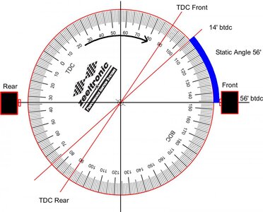
explained why a 56' degree SA works.
Thank You Beerdart!
Last edited:
All the new Zeels ship with 47 SA and I also confirmed with Borut through email.Because I am anal retentive and people are relying on me to tell them how
to build this.
Wax, my comments were directed towards Beerdart. I thought that was obvious.
I said in the beginning that I understood Storbeck's explanation of SA back in #805.
Your response was "Mint Answer" My problem was my specs for the reluctor didn't
jive with the 56 deg static angle (SA).
A problem with this thread is people have quoted multiple Kawasaki static angle
specs (47, 54, 56), even though the zeel came with instructions for a 56' SA. But now
we know how the 47' specs were determined.
I also posted my sketches, in the hope someone (maybe Wax) would confirm my
specs before we sent it to the machine shop, and nobody commented on them
except Beerdart. Unfortunately even Borut only restated the obvious.
Thankfully Beerdart posted his information and that info (and my measurements)
explained why a 56' degree SA works.
Thank You Beerdart!

- Location
- Riverside, CA
Actually, I'm still not sure, it sounds like you're making something custom.
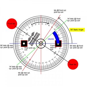
I am building a custom flywheel with 2 pickup coils for the Zeel PDCI-232. I am using a
PJS 750 aluminum flywheel used in the 93' world tour. The flywheel is a flat (platter style)
flywheel that is basically just a starter ring gear.
We made a new mount for the 2 pickup coils that mount to the front cover where the
stator used to be located.
The purpose for this system is to allow me to retard the rear cylinder.
That is why I posted pictures.
To be fair, I'm not sure how anybody would have read your comments and thought you were just
wondering what the correct static angle for a Kawasaki is.
I already knew the 56' spec, but I didn't understand how that spec worked until
Beerdart posted his picture.
Bill M.
Attachments
Last edited:
waxhead
wannabe backflipper
- Location
- gold coast
It doesn't matter what it is as long as its over the amount of timing your hoping to run. Once you have it on there put in a static angle of say 50 degrees. The put in a curve of 10 degrees and check with a light. You can then set the static angle then. If you want to run one cylinder retarded. then use a rotary table on the mill and machine off how many degrees you want on the front of the lump. This will make it fire the cylinder with that amount of retard. It will make a the timing curve jump a little on the light when you are setting it up but you will be able to see it. and you can do it with a single pickup and a cheaper zeeltronic cdi
If you are using two pickups then simply write a retarded curve for the rear cylinder and you dont need to worry about the length of the lump at all any more than just setting it in the ignition
I can not and will not say that the specs for the mechanical measurement is ok for a flywheel. Personally I think that Borut only says that to get you close which is why at the end he tells you to check with a timing light.
, I have a policy of not saying anything if i dont agree or dont know. In this case it was not agree.
However it could possibly work if you measured it 100% accurately and there was no delay in the ignition that ended up changing it. When i wrote the curve for the Yamaha cdi we are all using it was done off a timing light. When i wrote the one for the 550 ignitions i run i did it by mechanical measurement and found it to be 5 degrees out when i check with a light. Im not blaming anyone but myself and poor measurement for that, however i did decide from then on it was only ever going to be set by a timing light for me.
Last edited:
What did you end up with jetting wise?About 5-7 years ago I built a 5mm stroker. Ported etc for a friend, 46 mm mikuni b-pipe etc. I never got to tune it. However I was talking to him about the zeeltronic and got him interested. He pulled the pin and went for it. We put the wax2 curve in it and I rejeted his carbs. It walked my own surf ski so badly even I was shocked. He had eyes like saucers and was so happy. Like he had just had his first female ha ha. The change in the ski was outstanding. We had pulled out an enhancer and lightened flywheel
waxhead
wannabe backflipper
- Location
- gold coast
135 low
120 high
2.3 needle and seat
20 psi pop off
120 high
2.3 needle and seat
20 psi pop off
- Location
- Detroit metro
Question for you all that I should probably know the answer to. I was running a lightened charging GP flywheel with Wax's preinstalled curve. I swapped in my lightened TL flywheel but did not notice much power improvement over charging. Is there a different timing curve I should be using for TL vs charging, all other things being equal?
- Location
- Glenmoore pa
same curve. the difference is really only noticeable on the bottom end and its not very drastic. You'll get more bottom end "pop" with the TL FW in my experienceQuestion for you all that I should probably know the answer to. I was running a lightened charging GP flywheel with Wax's preinstalled curve. I swapped in my lightened TL flywheel but did not notice much power improvement over charging. Is there a different timing curve I should be using for TL vs charging, all other things being equal?
- Location
- Detroit metro
Yea, underwhelming for sure. I do feel slightly more low end with the TL FW but everything else feels about the same.
speedysprocket
Alex
- Location
- Chesapeake, VA
Yea, underwhelming for sure. I do feel slightly more low end with the TL FW but everything else feels about the same.
Who did your flywheel? Is it as light as can be...?
- Location
- Detroit metro
You did! I am quite happy with how light it is. My TL flywheel weighs 2 lbs 5 oz, and my lightened charging weighs 3 lbs 6 oz. I weighed stock as 4 lbs 2 oz, so its damn near half the weight of stock.


