Squarenose Project Back ON!!

F

Freestyleriverrat

Guest
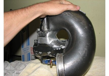
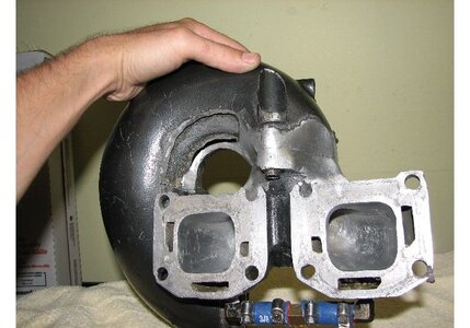
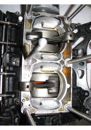
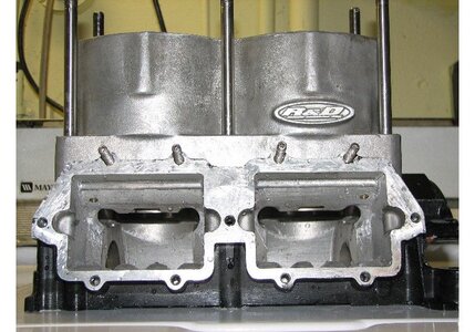
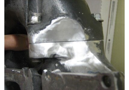
Head pipe: Front Cylinder

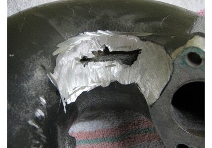
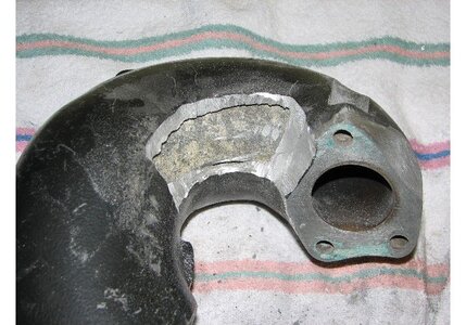
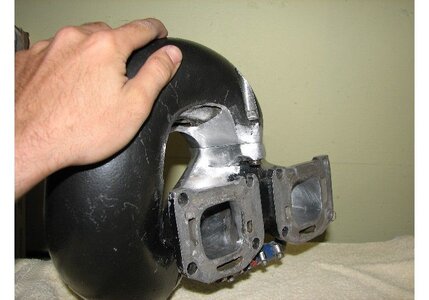
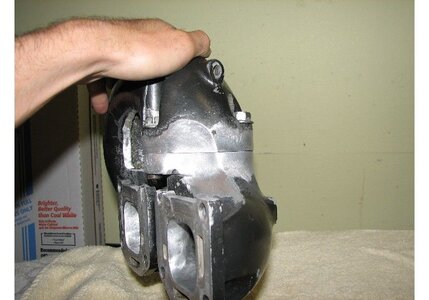
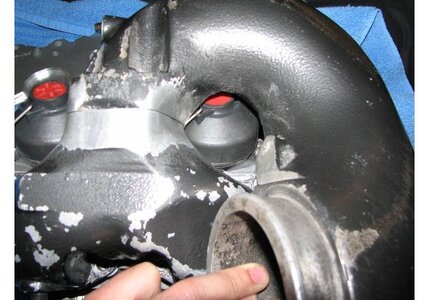
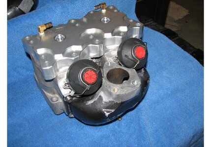
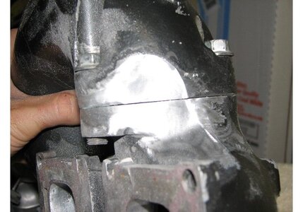
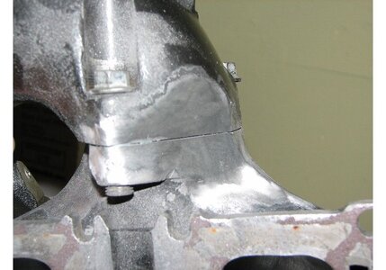
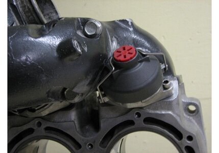
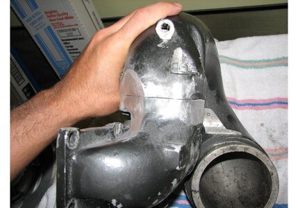
Once the manifold cleared the PV comfortably I just bolted the manifold to the head pipe and used a marker to trace a line on the bottom of the head pipe to give me a rough idea of where to start grinding. I used a 5in cut off wheel to gring away the big sections and used a 80 grit sanding bit followed by a 120 grit wheel. Took my time and was constantly checking and rechecking the fit. Used a sharpie to indicate where the valve hit, and did it a section at a time until the front PV cleared. I wante dto take my time on grinding b/c I want a smooth looking pipe.

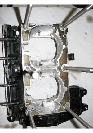
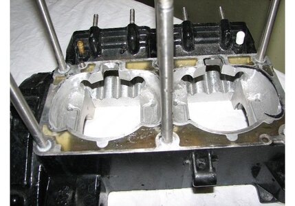
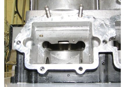
I can already tell the rear PV is going to be a pain and take twice as long. I will try and document that one well b/c I will be cutting into the water jacket which can be a little shakey for some guys (like myself). Paul charges $450 for this mod and it is worth every penny!!!!! I may have him weld my water jacket up when his shop is up and running.
 

Attachments

  • IMG_0856.JPG
    IMG_0856.JPG
    50.5 KB · Views: 85
  • IMG_0857.JPG
    IMG_0857.JPG
    73 KB · Views: 73
  • IMG_0858.JPG
    IMG_0858.JPG
    63.2 KB · Views: 85
  • IMG_0854.JPG
    IMG_0854.JPG
    62 KB · Views: 92
  • IMG_0861.JPG
    IMG_0861.JPG
    87 KB · Views: 96
Last edited by a moderator:
looking good, dude!

taking your time on that mod is the only way to do it right. once its all done, you can double up the head pipe gasket for some added clearance if necessary.
 
F

Freestyleriverrat

Guest
sflsurfrider said:
looking good, dude!

taking your time on that mod is the only way to do it right. once its all done, you can double up the head pipe gasket for some added clearance if necessary.

Thanks. Good idea on the gasket. I will look into that.
 
F

Freestyleriverrat

Guest
Head Pipe Mod: Rear Cylinder

For the most part I did 75% of material removal with a angle grinder and grinding wheel. The metal on the pipe is about a 1/4 in thick so it takes a while. Just keep checking a rechecking to see when you start breaking through. I am not done grinding on it to make it clear the PV but you get the idea. I am out of dremel bits so I am calling it a night :beerchug: I also am cleaning the pipe up and making the head pipe match the manifold to add a factory look to the mod. Hopefully when it is all done you will not be able to tell that a big a$$ grinder went to town on it.
 

Attachments

  • IMG_0865.JPG
    IMG_0865.JPG
    77.9 KB · Views: 125
  • IMG_0867.JPG
    IMG_0867.JPG
    108.6 KB · Views: 137
  • IMG_0869.JPG
    IMG_0869.JPG
    65.6 KB · Views: 105
  • IMG_0870.JPG
    IMG_0870.JPG
    65.6 KB · Views: 90
  • IMG_0872.JPG
    IMG_0872.JPG
    83.6 KB · Views: 108
Last edited by a moderator:
F

Freestyleriverrat

Guest
one more.........
 

Attachments

  • IMG_0874.JPG
    IMG_0874.JPG
    85.7 KB · Views: 125

pontoonkiller

bring back the wet bike
rat i'm not going to put my motor together till the winter so put the 5mil stroker in the lamey lets see what it will do
 
F

Freestyleriverrat

Guest
pontoonkiller said:
the power valves are from a seadoo but is it the 951 or 787

Dude..........you the Sea Doo mechanic you tell me :tomato: I am not sure what sea doo valves they are.......anyone? I am going to go ahead and rebuild them so that is good info to know.

pontoonkiller said:
rat i'm not going to put my motor together till the winter so put the 5mil stroker in the lamey lets see what it will do

I already stole that shiz and it's in my boat now :biggthumpup: :haha: JK
:noevil:
 

pontoonkiller

bring back the wet bike
i think that they are from a 951 do they seal with a gasket or an o-ring please take them off the cylinders and post some pics and i can tell you
 
F

Freestyleriverrat

Guest
pontoonkiller said:
i think that they are from a 951 do they seal with a gasket or an o-ring please take them off the cylinders and post some pics and i can tell you

Dude just come over :biggrin: the valves are not sea doo's valves but the bellows are.....out of a 785 http://www.x-h2o.com/threads/5859
 
F

Freestyleriverrat

Guest
For clearencing the PV's ended up having to clearence the PV cover itself. No big deal and it was something I was hoping to aviod doing but the adjuster was hittting the pipe, even with the waterjacket gone. Fits perfect now :Banane01: I am going to see if my buddy can weld it tomorrow.

Still in the process of checking tolerences, matching gaskets, making gaskets, checking fit and rejetting the carbs. More pics of the pipe will follow after it is welded and repainted.
 

Attachments

  • IMG_0908.JPG
    IMG_0908.JPG
    98.6 KB · Views: 112
  • IMG_0907.JPG
    IMG_0907.JPG
    86.8 KB · Views: 96
  • IMG_0893.JPG
    IMG_0893.JPG
    83.8 KB · Views: 103
  • IMG_0892.JPG
    IMG_0892.JPG
    107.3 KB · Views: 104
  • IMG_0905.JPG
    IMG_0905.JPG
    86.9 KB · Views: 121
F

Freestyleriverrat

Guest
I am getting ready to bust the cases apart and match the cylinder to the cases. As you can see in the pic there is a quite significant overlap that will IMO be a limiting factor on the setup and will not allow me to take full advantage of the improved/extra tranferports that the cylinder has. I will hopefully have the cases back togather later tonight. Pipe gets welded back tomorrow :biggthumpup: then all I have to do is assembly.
 

Attachments

  • IMG_0910.JPG
    IMG_0910.JPG
    71 KB · Views: 84
  • IMG_0912.JPG
    IMG_0912.JPG
    114.3 KB · Views: 91
F

Freestyleriverrat

Guest
still working on them and I am about 3/4 complete in this pic......off to HD to get more sanding bits :biggrin: Feeling much better now that the ports are not being obstructed by the cases.
 

Attachments

  • IMG_0915.JPG
    IMG_0915.JPG
    92 KB · Views: 73
  • IMG_0916.JPG
    IMG_0916.JPG
    89.1 KB · Views: 82
F

Freestyleriverrat

Guest
Couple more misc shot. I widened the porting on the cases to accomidate the increased angle that air will have to flow up into the transfer ports. This, in theroy should give the air a more direct shot to the ports directly above and off to the side of the reed cages. I am getting more anxious to get this thing on the water. It is just larger everywhere and I hope it is not a race ported lamey cylinder.....we will see. My buddy that was going to weld my pipe backed out so I may have to send it off to be welded. Gives me more time to make thing as perfect as possible I guess :rolleyes:

Took the time to clean the PV's really well. No more carbon build up on those.
 

Attachments

  • IMG_0925.JPG
    IMG_0925.JPG
    70.5 KB · Views: 91
  • IMG_0926.JPG
    IMG_0926.JPG
    103.4 KB · Views: 89
  • IMG_0928.JPG
    IMG_0928.JPG
    37 KB · Views: 76
F

Freestyleriverrat

Guest
No more zip ties to hold my fuel pump in place. made this bracket out of 6 layers of matt cloth and 1 layer of carbon. It is the first part I have made and I think it looks good considering. Need to clean the edges up a little but I am happy with it. Only took about 5 minutes to lay up.
 

Attachments

  • IMG_0931.JPG
    IMG_0931.JPG
    102.1 KB · Views: 96
F

Freestyleriverrat

Guest
Things are going good. I still need to have my pipe rewelded before I can start the motor. My dremel finally crapped out on me and I still have a little work left on the cases, but once I finish that and do a through wash down of all parts I can start the reassembly process. I have been slacking b/c the pipe. I have all the gaskets for the assembly, just need to finish it up.

Got my used TL system today and am in the process of rewiring it for a more sanatary appearence. I put it in the hull to see how everything would route and it was a mess. I am also mounting the coil and MSD box on insulated rubber mounts for vibration dampening. The TL will go in after I get the motor tuned and feel comfortable with adding more response. I am going to have to learn how to ride all over agian.
 

Attachments

  • IMG_0933.JPG
    IMG_0933.JPG
    103.7 KB · Views: 72
  • IMG_0935.JPG
    IMG_0935.JPG
    105.4 KB · Views: 69
F

Freestyleriverrat

Guest
Weighed the TL flywheel and the 61x flywheel that was lightened by Pro-tec.

The lightened flywheel weighed 3.28lbs or 1490g. The MSD TL flywheel weighed in at 1.75lbs or 795g. That is a 53% reduction in rotational mass over the lightend stock flywheel. Anouther thing I noticed was that the bulk of the weight on the stock flywheel was on the outside where the magnets are located (duhhhh). In contrast, the bulkof the MSD's weight is on the center of the flywheel. This also has a performance advantage over the stock unit by centering the bulk of the weight.
 

Attachments

  • IMG_0940.JPG
    IMG_0940.JPG
    96.1 KB · Views: 67
  • IMG_0941.JPG
    IMG_0941.JPG
    123.9 KB · Views: 63
Last edited by a moderator:
Top Bottom